Technical Knowledge
Laser leveling VS manual leveling for Superflat floors
April 28, 2026

If you are bidding on high-spec projects like Amazon fulfillment centers or automated cold storage, the "Manual vs. Laser" debate is already over. To hit Superflat (FM1/FM2) standards consistently, the human eye and a hand-held straightedge simply cannot compete with light-speed technology.
But why exactly is the shift happening globally? If you’re a contractor weighing the investment, here is the professional breakdown of Laser leveling vs. Manual leveling and why the "Vanse System" is the modern industry standard.
1. The Precision Gap: FF/FL Numbers Don't Lie
Manual leveling relies on the physical stamina of the crew. By the 4th hour of a pour, fatigue sets in, and those "tight" tolerances begin to slip.
Manual: Even the best crew will struggle to hit FF 30 consistently across a 1,000sqm slab.
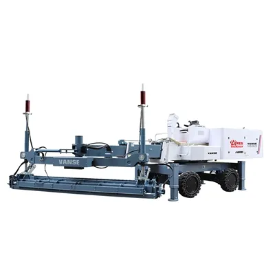
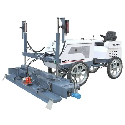
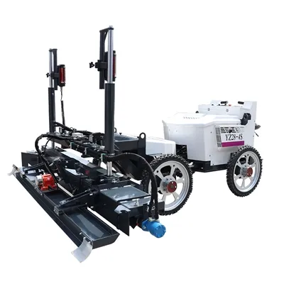
The Vanse Edge: A Vanse Concrete Laser Leveling Machine receives signals 10 times per second. It makes micro-adjustments to the hydraulic head in real-time. This automated precision is how you hit FF 50+ (Superflat) without breaking a sweat. It removes human error from the most critical stage of the pour.
2. The Efficiency Workflow: From Placement to Finish
A Superflat floor isn't just about the leveling; it’s about the entire "Value Chain." Manual crews often struggle with the sheer logistics of a large pour.
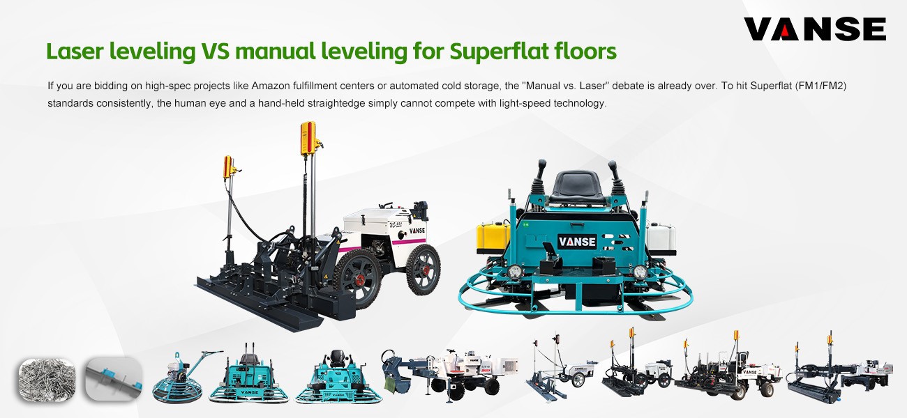
Placement: Instead of 6 guys with shovels struggling to move wet concrete, pros use a Vanse Concrete Distributor or a Mini Dumper. These tools place the concrete exactly where it needs to be, preventing the "mounds" that make leveling difficult.
Leveling: While the Laser Leveling Machine strikes off the floor, the Vanse Automatic Topping Spreader can follow behind to apply wear-resistant hardener with mechanical uniformity-something a manual thrower can never achieve.
Finishing: To turn that level slab into a mirror, you need torque. A Vanse Ride-on Power Trowel provides the heavy compaction needed to "burnish" the floor, closing the pores that manual floating leaves open
3. Labor Savings: From 12 Men to 5
In the international market, labor isn't just expensive; it’s hard to find.
The Math: A manual Superflat pour requires a "dream team" of 10–15 highly skilled laborers.
The Vanse Reality: With the right equipment, you can cut your specialized crew by 60%. One operator on the laser leveling, one on the Mini Dumper, and two on the Power Trowels. You produce 3x the square meters with half the people. The machine doesn't get tired, doesn't call in sick, and produces the same quality at 4 PM as it did at 8 AM.
4. Risk Management: Avoiding the "Grind"
If a manual floor fails the FF/FL test, your profits vanish into "rework" (grinding and patching).
Long-term Quality: Once the floor is set, a Vanse Concrete Cutting Machine (Floor Saw) ensures the joints are crisp and straight. This prevents the "spalling" and cracking that often plagues manually-leveled floors where the concrete wasn't consolidated uniformly.
Comparison Summary: Which One Wins?
| Feature | Manual leveling | Vanse Laser leveling System |
| Precision (FF/FL) | Variable (Human Error) | High/Superflat (Automated) |
| Production Speed | 400 – 600 m²/day | 2,500 – 3,500 m²/day |
| Labor Requirement | High (12+ people) | Low (4-6 people) |
| Surface Hardness | Uneven | Superior (Uniform Compaction) |
| Physical Strain | Extreme | Low (Machine-driven) |
| ROI | Low (High Labor + Rework Risk) | High (Speed + Guaranteed Spec) |
Final Word
Manual leveling belongs to the past. If you want to bid on the world's most demanding logistics and industrial projects, you need the precision of a Vanse fleet. From the initial transport with a Mini Dumper to the final pass of the Power Trowel, Vanse (www.vansemac.com) provides the technology to turn a simple concrete pour into a world-class asset.
Ready to upgrade your production? Explore the full range of Superflat solutions at Vanse Machinery and start hitting those high FF numbers today.
Note: The parameters provided in this document are for reference only and are not mandatory. Due to differences in technical characteristics between different brands and models of laser levelers, please consult the manufacturer for a suitable solution before actual operation. This reference document assumes no responsibility for any issues arising from failure to follow the manufacturer's instructions.
Thanks to All the Friends Who Support and Trust Shandong Vanse Machinery Technology Co., Ltd.
If you want to know more about Shandong Vanse Machinery Technology Co., Ltd. or have any questions, please feel free to contact us:
Our Factory
Shandong Vanse Machinery Technology Co., Ltd.


About the Author: Shandong Vanse Machinery Technology Co., Ltd.

Shandong Vanse Machinery Technology Co., Ltd. is a high-tech manufacturer specializing in concrete construction machinery, including laser screeds and related equipment. The company integrates R&D, production, and global sales, with products exported to over 60 countries and widely used in infrastructure projects worldwide.

Shandong Vanse Machinery
Leading manufacturer specializing in high-performance concrete laser screeds, telescopic arm flatwork handlers, and mechanical ride-on power trowels.
Post overview
Main PRODUCT Categories
Need Machine Guidance?
Speak directly with Shandong Vanse field specialists for tailored equipment quotes and site planning.
Contact Us TodayRelated Articles
You Might Also Like
November 26, 2025
Vanse Armor joint
In large-scale concrete floor projects such as industrial plants, logistics and warehousing centers, and large underground garages, joint treatment is the core link that determines the stability and service life of the floor structure. Conventional construction joints, due to their insufficient strength and weak resistance to deformation, are prone to problems such as misalignment, warping, and chipping, which seriously affect the load-bearing performance and functional use of the floor. As a specialized component specifically designed to address such issues, the structural design and application logic of armor joints are of crucial significance for enhancing the quality of floor engineering. Armor joint (also known as armor joint, armored joint, Bama joint, Ba Ma joint, zebra joint) is a composite structural component specially designed for strengthening the joint body of concrete floors. It is usually composed of high-strength metal substrates (such as galvanized steel plates, stainless steel plates, aluminum alloys, etc.), elastic sealing components (EPDM rubber strips, butyl rubber gaskets, etc.) and positioning and fixing systems (shear plates, anchor fasteners, support components). The edge of the seam is a straight metal/composite material cross-section. The upper and lower edges of the seam opening are flush with the ground/wall, without any additional curvature or inclination Angle, and the shape is simple. The edge of the seam is inclined to one side (the slope is usually 3°-5°), or both sides are beveled, forming a groove shape that is "low in the middle and high on both sides". It is advisable to pair it with more metal covers (such as stainless steel and galvanized steel plates). The top adopts an S-shaped curved surface design, formed by stamping steel plates. Combined with the force transmission plate and the telescopic sheath sleeve, it can achieve free expansion and contraction in both longitudinal and transverse directions. Triangular rib design: Triangular reinforcing ribs are welded on the outside of the steel plates of the sub-compartments to enhance the overall rigidity. Thick thrust plate: The thickness of the thrust plate can be selected from 6 to 12mm (material Q355), and it is suitable for heavy-duty areas above 80kN/m². Customized according to the diameter of the column, it is fixed with single-sided support, and the steel plates of the compartments surround the column to form a circular joint. The top edge guard is a flat steel plate, which is cut in the middle along a trapezoidal toothed curve, and the lower part is a punched and bent compartment steel plate and a sawtooth-shaped fixed plate. Cross-shaped, T-shaped, Y-shaped and other combined designs: They are used for the cross-connection of multiple Armor joints. For instance, a cross-shaped node Armor joint can simultaneously connect four straight seams. A stainless steel drainage ditch is integrated at the bottom of the Armor joint, and it is designed in an integrated manner with the steel plate of the compartment. The force transmission plate and the sheath are connected by sliding, allowing the floor to expand and contract freely when the temperature changes. Isolation joint: Also known as "structural separation joint", it is mainly used to achieve physical isolation between the concrete floor and the surrounding building structure. The applicable scenarios are the junctions between the floor and non-floor structures such as walls, reinforced concrete columns, equipment piers and abutments, and embedded part foundations. It separates two structures with different shrinkage coefficients and different load-bearing characteristics through joints, avoiding floor cracking caused by uncoordinated structural deformation. Elastic sealing materials (such as polyurethane sealant) are usually used for filling to ensure the separation effect and water resistance. Cutting joint: Also known as "shrinkage control joint", it is a preset joint body set up to address the problem of irregular cracks that are prone to occur after large-scale concrete pouring. The construction time is after the initial setting of the concrete and before the final setting (usually 24-48 hours after pouring, specifically adjusted according to the strength grade of the concrete). It is cut into shape with a special cutting machine, and the joint depth is usually 1/3 to 1/2 of the floor thickness. The joint spacing is determined according to the strength of the concrete and the ambient temperature (generally 4-6 meters). Its core function is to guide the concrete shrinkage stress to be concentrated and released at the preset joint, avoiding random cracks in the floor. Construction joint/partition joint: A construction joint is a temporary joint set at a preset position due to the excessive area of the floor pouring and the inability to carry out continuous construction at one time, used to divide the pouring sections. The partition joint is a permanent joint body that divides a large area of the floor into fixed-sized partition blocks to control the shrinkage and deformation of the floor in the long term. Essentially, both are "secondary pouring interfaces" of concrete. Such joints, due to the low bonding strength of the concrete joint surface and the uneven distribution of aggregates, have become weak links in the floor structure and are high-risk areas for diseases. Combining the characteristics of concrete structures with the force logic of the floor, the core reasons can be attributed to two points: The construction joint serves as the interface between two concrete pours. Due to the influence of the pouring interval time, the strength development of the concrete poured before and after is not synchronized, and the bonding force at the joint surface is insufficient. When the floor is subjected to vehicle rolling and equipment loads, the blocks on both sides of the joint body are prone to relative displacement, resulting in misalignment (height difference) or warping deformation. After the construction joint is opened, the concrete around the joint is prone to settlement of the internal aggregates under the action of vibration loads (such as vehicle passage and equipment operation), resulting in the separation of mortar and aggregates, and the density and strength of the concrete at the joint decrease. When the load exceeds the load-bearing limit of the joint concrete, edge cracking, corner chipping and other damages are prone to occur, and the damage will gradually expand after it occurs, affecting the structural stability of the entire silo block. Due to the inherent defects of construction joints, in projects with high requirements for the load-bearing capacity and durability of the floor, the use of armored joints has irreplaceable technical value. The metal frame of the armored joint can directly form a rigid connection with the concrete on both sides of the joint body, evenly transmitting the concentrated load at the joint to the surrounding floor, avoiding misalignment and warping caused by concentrated load. Meanwhile, the flexural and compressive properties of the metal substrate can effectively protect the joint concrete and prevent edge chipping caused by aggregate settlement. The elastic sealing components of the armored joint can accommodate the shrinkage deformation of the concrete floor (usually adaptable to ±5mm displacement) and slight settlement of the foundation. This not only prevents the joint from being cracked due to deformation but also ensures sealing performance, preventing oil stains and rainwater from seeping into the foundation. Traditional construction joints need to be repaired on average every 3 to 5 years (such as removing damaged concrete and refitting sealant), and in severe cases, local rework is required. The armored seam, with the anti-corrosion performance of the metal substrate (galvanization, anodizing treatment) and the aging resistance of the sealing components, can have a service life of 15 to 20 years, significantly reducing the frequency and cost of later maintenance. The layout of the armor joints should be determined comprehensively in combination with the floor structure form, load characteristics and usage scenarios. The core should follow the following five technical principles to ensure the effective performance of its functions: Arrange the Armor joints laterally along the load-bearing columns to divide the floor into independent compartments. The size of each compartment must be strictly controlled within 30m×30m. Exceeding this size will cause the shrinkage stress of the concrete to exceed the bearing limit of the armor joint, which is prone to cause cracking in the middle of the silo block. It is strictly prohibited to arrange Armor joints along the direction of directional main channels (such as forklift channels in logistics warehouses and entry and exit lanes in garages) – to prevent vehicle tires from long-term rolling along the seam opening, accelerating the wear of sealing components and deformation of the seam opening. It can be arranged perpendicularly to the direction of the passage to ensure smooth vehicle passage. The length-to-width ratio of floor compartments should be controlled within 1:1.5. If the aspect ratio is too large (such as 1:2 or above), the warehouse blocks are prone to torsional stress due to unidirectional contraction, which may lead to the failure of the Armor joint sealing assembly or the deformation of the metal frame. When armor joints encounter reinforced concrete columns, walls, equipment foundations and other structural bodies, a avoidance distance of 50-100mm should be reserved to prevent the deformation of the structural body and the floor from interfering with each other, which may cause the joint to be squeezed and damaged. Regardless of whether the floor adopts the form of soil foundation bearing or pile foundation bearing, PE sliding film must be laid at the contact surface between the floor and the foundation as well as the contact surface between the floor and the pile cap. PE sliding film can reduce the adhesion between concrete and the base layer, prevent floor cracking caused by foundation settlement, and at the same time provide a stable positioning reference for armor joints, ensuring installation accuracy. In line with the requirements of engineering applications, compared with traditional construction joints and cutting joints, armored joints have the following irreplaceable functional advantages: The metal frame can withstand a uniformly distributed load of 3-5 tons per square meter, making it suitable for high-frequency load scenarios such as heavy-duty forklifts and freight vehicles. The concrete at the joint will not crack due to concentrated loads. It can accommodate ±5mm contraction displacement of concrete floors and ±3mm settlement displacement of the foundation. The elastic sealing components expand and contract synchronously with the deformation, always maintaining the sealed state of the joint. The metal frame forms a "rigid constraint" on the concrete around the joint, preventing aggregate settlement and mortar loss caused by vibration, and fundamentally solving the problems of chipped edges and broken corners. It can be adapted to different types of foundation floors such as soil foundation and pile foundation, and achieve precise fixation in combination with PE sliding film. The installation process is seamlessly connected with the floor pouring procedure, without the need for additional complex processes. The metal substrate undergoes anti-corrosion treatment (galvanizing, anodizing), featuring strong weather resistance and rust resistance. The sealing components are made of anti-aging rubber material, with a service life of over 15 years, significantly reducing the later maintenance cost of the floor. When installing expansion joints, it is essential to meet the requirements of the floor design for levelness and straightness. During the installation process, a level should be used for inspection to ensure that they are precisely vertical in the vertical direction. The force transmission plate should be kept level so that it can slide freely within the plastic sheath when the floor expands and contract freely without generating resistance. In addition, a laser or optical level should also be used for level control and inspection. Step 1 Use nylon thread to position the designed expansion joint. With the assistance of the installation bracket, the straightness and levelness of the Armor joint are adjusted using an optical level until the design value is reached. Step 2 Start installation from the column or wall, and the Armor joint can only be fixed on one side. Use short-threaded steel bars with a diameter of 12 to 14mm to drive into the foundation on one side of the armor joint. Drive two fixed steel bars into each support position, and then weld the armor joint to the fixed steel bars with short steel bars with a diameter of 12mm to 14mm. Step 3 On the first day, pour the unsupported side. The next day, remove the supports and cut off the fixed reinforcing bars above the base layer (to prevent the floor and foundation from being locked and unable to expand or contract freely due to the presence of the fixed reinforcing bars). And pour the concrete on the other side of the armor joint. Step 4 When the curing period of the concrete is over, the edge steel of the armor joint will be gradually and naturally pulled apart. After the contraction stabilizes, remove the garbage in the joint, then fill the elastic adhesive, clean and protect the construction site, and cure for more than 3 days. As a key component for enhancing the quality of concrete floor engineering, the application value of armor joints lies not only in solving the disease problems of traditional joints, but also in improving the long-term stability and load-bearing reliability of the floor structure through standardized structural design and standardized layout principles. For engineering practitioners, it is necessary to strictly follow core principles such as "control of compartment size, reasonable avoidance of passageways, and avoidance of structural structures", and select models in combination with the usage scenarios of the floor and the conditions of the foundation. Only in this way can the technical advantages of the armor joint be fully exerted, and the construction quality and full life cycle value of the floor project be fundamentally improved. Note: The parameters provided in this document are for reference only and are not mandatory. Due to differences in technical characteristics between different brands and models of laser levelers, please consult the manufacturer for a suitable solution before actual operation. This reference document assumes no responsibility for any issues arising from failure to follow the manufacturer's instructions.Read More
January 2, 2025
When writing about concrete laser screed machines, what research methods or data analysis tools can help us more accurately evaluate their performance?
– Using level and tower ruler: On the ground after the concrete laser leveling machine is constructed, set measurement points at a certain interval (such as every 1 meter or 2 meters). Use the level and tower ruler to measure the elevation of each point, and then calculate the flatness indicators of the ground, such as maximum deviation, mean square error, etc. This method can intuitively evaluate the control ability of the leveling machine on the flatness of the ground. For example, in a factory floor construction project, the ground after the laser leveling machine is measured. If the maximum deviation is within the allowable range (such as within 3-5mm of the industrial floor flatness requirement), it means that its flatness performance is good. – Laser scanner: The laser scanner can quickly obtain three-dimensional data of a large area of ground. Place the laser scanner in a suitable position, scan the ground after construction, and obtain the point cloud data of the ground. By processing these data with professional software, a three-dimensional model of the ground can be generated, and parameters such as the flatness and slope of the ground can be accurately calculated. Compared with levels and tower rulers, laser scanners are more efficient and can obtain more comprehensive data. – Concrete test block production and compression test: During the construction of the laser leveling machine, concrete test blocks are produced at the same time. The production conditions of these test blocks (such as concrete mix ratio, vibration method, etc.) should be consistent with the construction site. After the test blocks reach the specified curing period, the test blocks are tested for compressive strength using a pressure testing machine. By comparing the compressive strength of the test blocks with the design strength requirements, it is evaluated whether the construction process of the laser leveling machine has an impact on the strength of the concrete. For example, if the design requires the compressive strength of the concrete to be C30, after testing, the average compressive strength of the test blocks reaches or exceeds 30MPa, and the discreteness is small, indicating that the construction of the leveling machine has little effect on the strength and the performance is reliable. – Rebound Hammer Test: On the concrete surface after construction, a rebound test is performed using a rebound hammer. The rebound hammer infers the strength of the concrete by hitting the concrete surface and based on the rebound value. This method is easy to operate, and can be used to perform multi-point tests on a large area of concrete surface to quickly evaluate the strength uniformity of the concrete. However, the results of the rebound test are affected by factors such as the surface quality of the concrete and the depth of carbonization, and need to be comprehensively judged in combination with methods such as the test block compression test. – Construction time record: In concrete construction projects of different scales (such as different areas and thicknesses), record the time it takes for the laser leveler to start construction and complete the leveling task. At the same time, record the pause time during the construction process (such as equipment failure maintenance, material supply interruption, etc.), and evaluate its construction efficiency by calculating the amount of work completed per unit time (such as square meters/hour). For example, in a 1,000 square meter ground construction, if the laser leveler completes the construction in 8 hours without any fault, its construction efficiency is 125 square meters/hour. – Comparative test: Compare the concrete laser leveler with the traditional leveling method (such as manual vibration, small mechanical vibration, etc.) under the same construction conditions (such as the same amount of concrete, the same site environment, etc.). Record the respective construction time, manpower input, energy consumption and other data, and highlight the efficiency advantage of the laser leveler through comparative analysis. – Data collation and descriptive statistics: Input the data obtained from the experimental test (such as flatness measurement value, strength test value, construction time, etc.) into the statistical analysis software. Use the data collation function of the software to clean and preprocess the data to remove outliers, etc. Then perform descriptive statistical analysis to calculate statistical indicators such as mean, standard deviation, maximum value, minimum value, etc. to understand the central trend and dispersion of the data. For example, through the Excel data analysis plug-in, calculate the mean and standard deviation of the flatness measurement data to intuitively display the overall situation and fluctuation range of the ground flatness. – Correlation analysis: When studying the relationship between different performance indicators of the laser leveling machine, such as between construction efficiency and flatness, between construction time and strength, etc., statistical analysis software can be used for correlation analysis. By calculating the correlation coefficient, it is determined whether the two indicators are positively correlated, negatively correlated, or unrelated. For example, if a negative correlation is found between construction time and flatness, that is, the shorter the construction time, the worse the flatness, the further analysis of the cause is needed. It may be that the construction speed is too fast and affects the leveling effect. – 3D modeling and visualization analysis: Use software such as AutoCAD Civil 3D to import the ground 3D point cloud data obtained by the laser scanner to generate a high-precision ground 3D model. Through this model, you can intuitively view the flatness and slope of the ground, and perform virtual roaming and spatial analysis. For example, in concrete construction on complex terrain, the 3D model can accurately evaluate whether the laser leveling machine has completed the slope shaping of the ground according to the design requirements. – Structural analysis (for concrete structure performance): For situations involving concrete structure performance evaluation, such as the bearing capacity of large concrete slabs, use structural analysis software such as Midas Gen. Input the concrete structure parameters (such as thickness, strength, etc.) after the laser leveling machine is constructed into the software, and combined with the actual load conditions, structural mechanics analysis is performed to evaluate the safety and reliability of the structure. This kind of analysis is very important for some concrete projects with high requirements on bearing capacity (such as parking lots, industrial plant floors, etc.).Read More
June 12, 2025
How to improve the safety of concrete laser leveling machine?
Operator safety training and qualification management 1. Professional training requirements Certification required: Operators must pass the training of manufacturers or professional institutions, master the equipment principles, operation procedures and emergency shutdown methods, and hold valid certificates to work after passing the assessment. Regular refresher training: Safety operation refresher training is carried out every six months, focusing on strengthening practical skills such as coping with new working conditions (such as slope operation, night construction), emergency handling of equipment abnormalities, etc. Case warning education: Analyze typical accident cases in the industry (such as leveling beam falling, laser system misjudgment leading to collision), and clarify the hazards of illegal operations. 2. Safety awareness training It is strictly forbidden to work after drinking or fatigue, stay focused during operation, and it is forbidden to make phone calls or distracted operations during operation. Establish a "double confirmation" system: key actions (such as equipment displacement, parameter modification) require two people to check and confirm to avoid single-person misoperation. Equipment safety protection device upgrade and maintenance 1. Mechanical safety protection Emergency stop button The machine body and operating handle are equipped with red emergency stop buttons. When pressed, the power system is immediately cut off, and the response time is ≤0.5 seconds. Anti-fall protection The leveling beam lifting system is equipped with a double brake device (hydraulic lock + mechanical lock). When the hydraulic system fails, the mechanical lock automatically locks to prevent the beam from falling. Overload protection The hydraulic system is equipped with a relief valve, which automatically relieves the pressure when the pressure exceeds 110% of the rated value; the motor is equipped with an overload protector to prevent the motor from being burned by excessive current. Protective cover for moving parts Metal protective covers are installed on rotating parts such as chains and pulleys. The protective covers must pass the 100N force test without deformation to prevent people from contacting and getting injured. 2. Electrical and laser system safety Leakage protection: The electrical system is equipped with a leakage circuit breaker (operating current ≤30mA, operating time ≤0.1 second), and the cable joints are waterproof and sealed to prevent rainwater from seeping in and causing electric shock. Laser safety level: Use Class 3B or lower laser transmitters (wavelength 630-670nm, power ≤50mW), avoid direct exposure to human eyes, and set up "Laser Danger" warning signs in the operating area. Anti-electromagnetic interference: The control system line uses shielded cables, away from interference sources such as electric welders and high-frequency equipment, to prevent laser signal misjudgment from causing equipment out of control. Safety management specifications for the working environment 1. Site pretreatment Survey the site before construction, remove hidden dangers such as underground pipelines, steel bar heads, and water pits, and lay steel plates (thickness ≥ 20mm) on soft ground to prevent the equipment from sinking and rolling over. Define the working area, set up cordons and warning signs, and keep non-operating personnel at least 5 meters away from the equipment to avoid collision when the leveling beam rotates. 2. Safety measures for special working conditions Night/low-light operation: Install LED work lights (brightness ≥ 200lux) to ensure that there is no shadow in the operating area; add reflective signs to the laser receiver to assist manual observation of the equipment position. Slope operation: When the slope exceeds 5°, the stability of the equipment must be tested first (run without load for 10 minutes), and the walking speed must be controlled to ≤1.5km/h during operation to avoid sudden stops and sudden turns. Rainy days/humid environment: Stop open-air operations. If construction is necessary, check the waterproof performance of electrical components, and operators must wear insulating shoes and gloves. The grounding resistance of the equipment must be ≤4Ω. Operation process safety control 1. "Three-step inspection" before operation Mechanical inspection: Test the lifting and traveling system of the leveling beam to confirm that there is no jamming in each action and the pressure of the hydraulic system is normal (the pressure gauge shows within the rated value ±0.5MPa). Electrical inspection: Test the calibration accuracy of the laser system (target ruler measurement error ≤3mm), check whether the sensor signal transmission is stable, and the backup battery power is ≥80%. Safety device test: Press the emergency stop button to confirm that the equipment stops immediately; simulate the loss of pressure in the hydraulic system to verify whether the mechanical lock starts automatically. 2. Key points for safe operation during operation It is forbidden to climb the fuselage or adjust the components when the equipment is running. When maintenance is required, the equipment must be shut down and the power must be cut off. When transferring the site, the leveling beam must be raised to the lowest position and locked, the driving speed must be ≤5km/h, and the height and weight limit must be confirmed before passing through the bridge and tunnel (equipment height + 0.5m safety margin). When multiple people work together, a dedicated person should be assigned to direct, and an intercom (fixed channel) or hand signals (such as the "stop" gesture is to extend the arm horizontally forward) should be used to avoid communication errors. V. Safety regulations in maintenance 1. Power-off and sign-out system Before maintenance, turn off the main power switch and hang a "no closing" warning sign. The key is kept by the maintenance personnel to prevent accidental start-up. Hydraulic system pressure relief: Loosen the cylinder exhaust valve and confirm that the pressure drops to 0MPa before disassembling the pipeline to avoid high-pressure oil spray and injury. 2. High-altitude work protection When inspecting the laser transmitter (height ≥ 2 meters), use an anti-slip ladder (load bearing ≥ 150kg) or a lifting platform, and the operator wears a safety belt (hook fixed to an independent anchor point). It is forbidden to stand or walk on the leveling beam. When the beam needs to be inspected, it needs to be supported by a safety bracket (support point load bearing ≥ 1.5 times the weight of the equipment). Emergency response and safety plan 1. Emergency response process for sudden failures Fault type Emergency measures Laser system failure Immediately switch to manual mode, stop operation, evacuate personnel, and notify technicians to calibrate or replace the receiver. Hydraulic system oil leakage Turn off the engine, surround the oil leak area with sandbags to prevent spread, use oil-absorbing cotton to clean, and strictly prohibit open flames from approaching (hydraulic oil ignition point ≥ 180℃). Risk of equipment tipping over Operators immediately evacuate to a safe area, slowly reset with a jack (the support point must be at the specified position of the frame), and it is strictly forbidden to force the equipment to start. 2. Safety plan and drills Formulate the "Laser Leveler Safety Accident Emergency Plan", clarify the handling procedures for electric shock, mechanical injury, laser burns, etc., and equip first aid kits (including tourniquets, burn ointments, etc.). Organize emergency drills every quarter to simulate scenarios such as equipment out of control and personnel injuries, improve the team's response speed, and archive the drill records for future reference. Strengthening the safety management system Daily inspection form: Formulate an "Equipment Safety Inspection Form", which includes 20 inspection items such as braking system, lighting, safety devices, etc., and the operator signs and confirms before daily operation. Responsibility traceability mechanism: Incorporate safety indicators into the performance appraisal of operators. For those who violate the regulations and cause accidents, deduct bonuses or pursue legal liability according to the degree of responsibility. Technology upgrade investment: Regularly update equipment safety modules (such as installing GPS positioning anti-crossing system and blind spot camera), and use intelligent monitoring system to warn abnormal data in real time (such as alarm when hydraulic oil temperature exceeds 90℃). Through the above measures, the operation risk of concrete laser leveling machine can be systematically reduced. It is recommended to combine the equipment instruction manual and industry safety standards (such as GB 2894-2008 "Safety Signs and Guidelines for Their Use"), formulate a personalized safety manual, and continuously track the application of new technologies (such as AI visual anti-collision system) to dynamically improve the level of safety protection.Read More