Technical Knowledge
What is the efficient of a large concrete trowel?
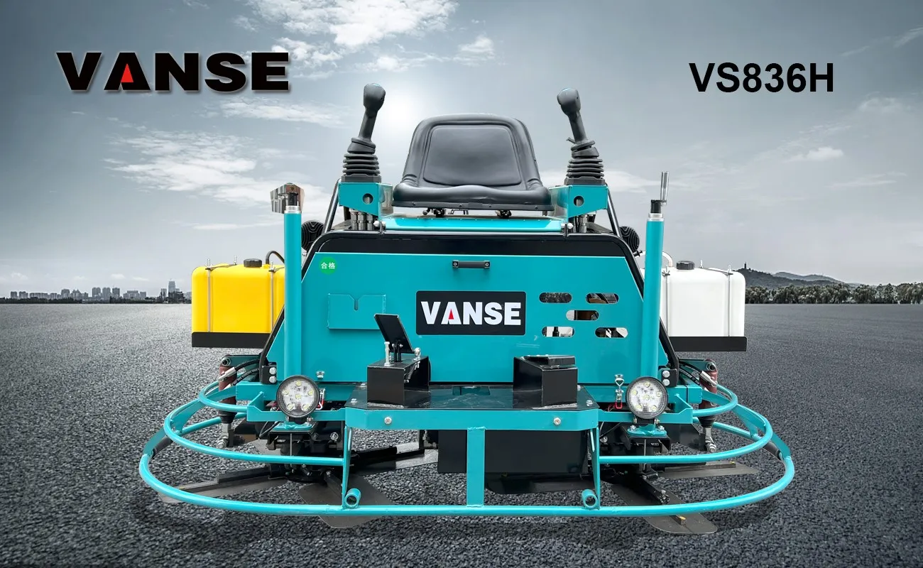
The working efficiency of large concrete trowels varies depending on factors such as model, configuration and construction conditions. The working efficiency of common ride-on double-disc trowels is generally around 400-500 square meters per hour. Calculated on an 8-hour workday, its working efficiency is between 3000-5000 square meters.
Thanks to All the Friends Who Support and Trust Shandong Vanse Machinery Technology Co., Ltd.
If you want to know more about Shandong Vanse Machinery Technology Co., Ltd. or have any questions, please feel free to contact us:
Our Factory
Shandong Vanse Machinery Technology Co., Ltd.








Share this article

About the Author: Shandong Vanse Machinery Technology Co., Ltd.
Shandong Vanse Machinery Technology Co., Ltd. is a high-tech manufacturer specializing in concrete construction machinery, including laser screeds and related equipment. The company integrates R&D, production, and global sales, with products exported to over 60 countries and widely used in infrastructure projects worldwide.
Previous Post
Next Post
Related Articles
You Might Also Like
How to match concrete power floats with laser leveling for high-precision warehouse floor projects
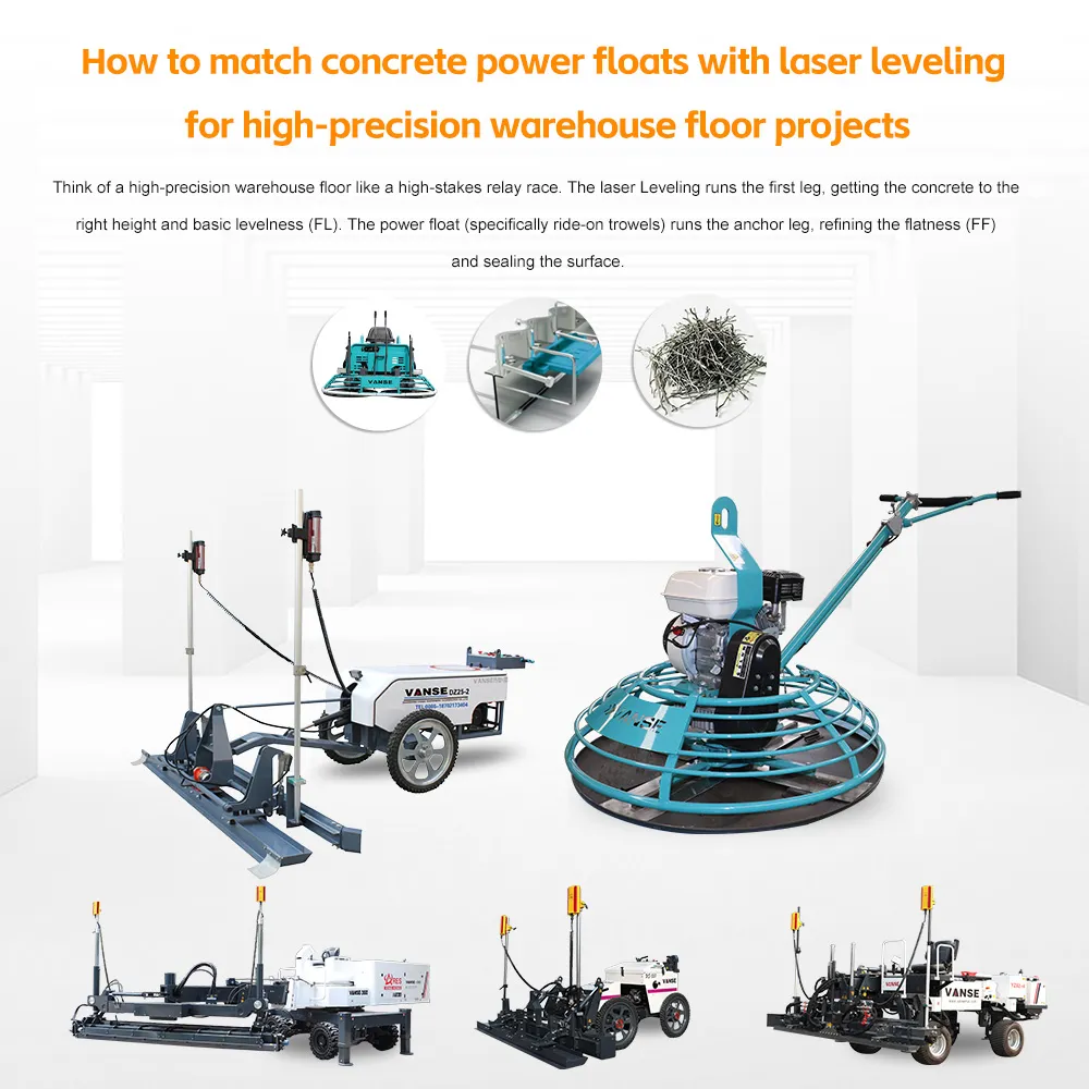
Think of a high-precision warehouse floor like a high-stakes relay race. The laser Leveling runs the first leg, getting the concrete to the right height and basic levelness (FL). The power float (specifically ride-on trowels) runs the anchor leg, refining the flatness (FF) and sealing the surface. If these two machines aren't perfectly "matched" in timing and technique, you'll end up with a floor that is level across the building but bumpy under a forklift. Here is how to synchronize them for elite results. For high-precision (Superflat) projects, weight is your friend. While walk-behind floats are fine for small shops, warehouse floors require heavy-duty ride-on power trowels. These machines provide the necessary downward pressure to "cut" high spots and "fill" low spots left by the Leveling. Machine Role Laser Leveling (The Macro) Power Float (The Micro) Primary Goal Elevation & Levelness (FL) Flatness & Density (FF) Key Component Laser receiver & Augers Float pans (Clip-on) Timing Immediate (Wet/Plastic) Delayed (Walkable/Plastic) Correction Moves bulk material Shaves "micro-waves" The most critical "match" between the Leveling and the float happens during the panning phase. * The Pan: Instead of using individual blades, you clip large, flat steel disks (pans) onto the bottom of the power float. The Synergy: The laser Leveling leaves a "closed" surface, but it's never perfectly flat. The pans act as a giant plane. Because the ride-on float has a wide wheelbase, the pans cannot fall into small dips; they "bridge" them and shave the peaks. The Technique: To maximize precision, the operator should run the power float perpendicular to the direction the laser Leveling traveled. This cross-cutting action cancels out any rhythmic waves the Leveling may have left behind. A laser Leveling is fast-it can place 20,000 square feet in a few hours. If your power floating crew can't keep up, the concrete will "get away" from them. The "Footprint" Test: You shouldn't start power floating until a man can stand on the concrete and leave a footprint about 3 mm to 6 mm deep. Matching the Pace: For every laser Leveling on-site, you typically need at least two high-speed ride-on trowels to ensure the entire slab is panned and finished within the same moisture window. If the concrete hardens unevenly, the float will "bounce" over high spots rather than cutting them. One common mistake is over-floating the edges or the areas around columns. The Problem: Power floats naturally want to "dig in" at the edges. The Match: High-precision projects use hand-leveling tools (like a 10-foot highway straightedge) in tandem with the power float. After the first pass of the float, a worker "restraightens" the floor manually to ensure the float didn't create any new "dishes" while trying to fix the old ones. Use Clip-on Pans: Never use just blades if you are chasing high FF numbers. Cross-Pass Pattern: Always float at a 90-degree angle to the laser Leveling's path. Non-overlapping Passes: Ensure the float operator maintains a consistent overlap (usually 50%) to prevent creating new ridges. Monitor Blade Pitch: As the floor hardens, increase the blade pitch gradually. Moving too fast to a high pitch can "chatter" the surface, ruining the flatness the laser Leveling worked so hard to establish. Pro Tip: On Superflat jobs, use a Floor Profiler (like a Dipstick) between floating passes. This allows the team to identify a low spot while the concrete is still "green" enough to be corrected with the power float. Would you like to see a step-by-step "Finishing Schedule" that outlines exactly when to switch from pans to combo blades for maximum floor density? Contact us NOW Note: The parameters provided in this document are for reference only and are not mandatory. Due to differences in technical characteristics between different brands and models of laser levelers, please consult the manufacturer for a suitable solution before actual operation. This reference document assumes no responsibility for any issues arising from failure to follow the manufacturer's instructions.How does the concrete laser leveling machine ensure the work effect and quality during the leveling process?
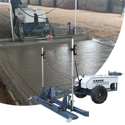
As a key equipment in modern building construction, the concrete laser leveling machine's leveling effect and quality directly affect the flatness and service life of the concrete floor. In order to ensure the work effect and quality during the leveling process, fine control and operation are required from multiple dimensions. •••▶ Preparation before operation ◀••• 1. Site Assessment: Before starting grading work, conduct a detailed assessment of the construction site. Check the basic condition of the ground, including the pouring quality, flatness, strength, etc. of the concrete. Understanding the condition of the ground will help you choose the appropriate leveling method and parameters. 2. Equipment inspection: Conduct a comprehensive inspection of the concrete laser leveling machine to ensure that the equipment is in good working condition. Check key components such as laser systems, power systems, transmission systems, and control systems to ensure that they can operate normally and provide stable performance. 3. Set parameters: Set appropriate leveling parameters according to construction requirements and ground conditions. This includes adjustments to the laser system, leveling speed, leveling depth, etc. The setting of parameters should take into account the flatness of the ground, construction efficiency and quality requirements. •••▶ Operations during leveling ◀••• 1. Maintain a stable traveling speed: During the leveling process, the operator should maintain a stable traveling speed. Avoid speeds that are too fast or too slow to avoid affecting the leveling effect and quality. A stable travel speed helps ensure uniform force on the ground, reducing unnecessary fluctuations and errors. 2. Adjust the laser system in time: The laser system is the core component of the mixed soil laser leveling machine and provides accurate leveling reference lines. During the leveling process, operators should pay close attention to the status of the laser system and adjust the height and position of the laser line in a timely manner to ensure leveling accuracy and stability. 3. Even distribution and vibration: Before leveling, the concrete should be evenly distributed and vibrated. The fabric should be even and avoid any accumulation or voids. Vibration should be sufficient to improve the compactness and strength of the concrete. 4. Control the leveling depth: The leveling depth is an important factor affecting the leveling effect and quality. Operators should control the leveling depth according to ground conditions and construction requirements. Leveling that is too deep will cause the ground to be too thin, affecting the strength and flatness; leveling that is too shallow will not be able to effectively eliminate uneven ground problems. 5. Pay attention to observation and adjustment: During the leveling process, the operator should always pay attention to the changes in the ground. If problems such as waves, bulges or depressions are found on the ground, leveling parameters should be adjusted in time or other measures should be taken to repair them. •••▶ Quality control after leveling ◀••• 1. Ground inspection: After the leveling work is completed, a comprehensive inspection of the ground should be carried out. Check the flatness, levelness, verticality and other indicators of the ground to ensure that it meets the construction requirements. If problems are found, they should be repaired and adjusted in time. 2. Test block production and testing: According to the construction requirements, test blocks are made and corresponding strength and durability tests are performed. Through the test results of the test blocks, the quality and performance of the concrete during the leveling process can be evaluated. 3. Maintenance: After the leveling work is completed, the concrete laser leveling machine should be cleaned and maintained in a timely manner. This helps extend the life of the equipment and ensures stable performance the next time you work on it. •••▶ People skills and training ◀••• 1. Improve operating skills: Operators should have good operating skills and be able to master the operating essentials of the concrete laser leveling. Through regular training and skill assessment, the skill level of operators can be improved and the stability and accuracy of the leveling process can be ensured. 2. Enhance quality awareness: Operators should fully understand the importance and quality requirements of leveling work. By strengthening quality education and publicity, operators will increase their sensitivity and attention to quality issues, thereby paying more attention to details and quality control in their work. •••▶Coordination with other construction links ◀••• 1. Coordination with the pouring process: The leveling work of the concrete laser leveler is carried out after the concrete is poured. Therefore, coordination with the pouring process is crucial. Pouring should ensure that the concrete is evenly distributed and free of bubbles and voids, providing a good foundation for leveling work. 2. Connection with subsequent maintenance: After the leveling work is completed, subsequent maintenance work needs to be carried out, such as watering, covering, etc. Work closely with the street coordinators in the subsequent maintenance process to ensure that the ground is not damaged during the maintenance process and remains in good condition. •••▶Technical updates and equipment upgrades ◀••• 1. Pay attention to new technologies and equipment: With the advancement of science and technology and the development of the construction industry, new leveling technologies and equipment are constantly emerging. Pay attention to the development of new technologies and new equipment, and timely introduce and apply advanced technologies and equipment that suit your own construction needs, which will help improve the leveling effect and quality. 2. Regularly update and upgrade equipment: As construction equipment, concrete laser levelings may experience performance degradation or technological backwardness as their usage time increases and technology advances. Therefore, regular updates and upgrades of equipment are necessary. By updating and upgrading equipment, the advancement and stability of the equipment can be maintained, and the leveling effect and quality can be improved. In summary, ensuring the working effect and quality of the concrete laser leveling machine during the leveling process requires preparation before operation, operation during the leveling process, quality control after leveling, personnel skills and training, and other construction We will start from various aspects such as coordination of links, technology updates and equipment upgrades. Through comprehensive policy implementation, precise management and continuous improvement, the leveling effect and quality can be effectively improved to meet construction requirements and user expectations.Introduction to the basics of slipform machine construction
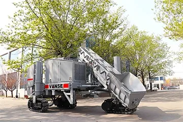
After the concrete is faced with the fixed mold, the sliding mold makes the concrete form. Used for road shoulder synovial film operation, drainage ditch synovial film operation, curb forming operation, etc. This type of machine is based on the carrier that meets the engineering standards, including asphalt products and cement concrete road construction on both sides of the curb and drainage ditches and other facilities The special industry equipment consists of walking mechanism, vibration mechanism, forming mechanism, generator and power distribution, etc. The operation process of the sliding form machine is that the concrete is vibrated and compacted by the vibrating rod, and then formed by the sliding form of the mold, and the continuous operation is carried out while walking. The shaped curb has high impact strength and stability. It can be widely used in: highways, highways, airports and other places. It is fully mechanically operated, saving a lot of labor costs, and is a new type of sliding membrane construction standard.