Technical Knowledge
How can the concrete laser leveling machine components (such as laser emitters) be maintained to extend their service life
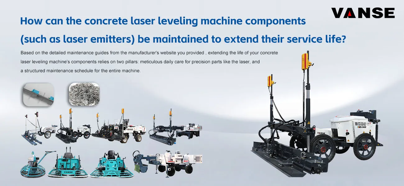
Based on the detailed maintenance guides from the manufacturer's website you provided , extending the life of your concrete laser leveling machine's components relies on two pillars: meticulous daily care for precision parts like the laser, and a structured maintenance schedule for the entire machine.
Here is a practical guide focused on the key components you asked about.
🔧 Core Maintenance for Laser System Components
The laser emitter and receiver are the most sensitive parts. Their maintenance revolves around cleanliness, careful handling, and regular accuracy checks .
| Component | Daily Care Essentials | Calibration & Advanced Care |
| Laser Emitter | Clean the lens gently after each use with special lens paper or a blower ever use rough materials . |
Perform a self-check before key projects: Set it up, allow it to self-level, then verify accuracy by checking beam height at two distances (e.g., 5m and 15m). The height difference should be near zero .
Check laser tube brightness every 300-500 hours. Replace if the beam is weak or range shortens . |
| Wipe the body with a dry cloth . | ||
| Always store in its dedicated, foam-padded box to prevent shock . | ||
| Use and store in a cool, dry place . | ||
| Manage battery: Avoid deep discharge; charge every 1-2 months during long storage . | ||
| Laser Receiver & Sensors | Keep the sensor lens clean and free of mud . |
Perform linkage calibration: After the emitter is set, calibrate the receiver with the control panel. Slowly raise/lower the receiver rod and record the "high" and "low" points so the machine responds correctly .
Adjust sensitivity based on site conditions (e.g., higher in bright sunlight) for optimal signal capture . |
| Secure the mounting to prevent loosening from vibration . | ||
| Handle the receiver rod carefully to avoid bending . | ||
| Inspect cables daily for damage or loose connections, as these cause signal issues . |
⏱ A Structured Maintenance Plan for the Whole Machine
To keep the laser system and the rest of the machine in top condition, follow a maintenance plan based on operating hours. The table below integrates recommendations from your provided sources .
| Frequency | Key Actions for Longevity |
| Daily (After Each Use) | Thoroughly clean all concrete residue from the Leveling head, vibrator, frame, and especially the laser components . |
| Inspect for leaks, loose bolts, and any visible damage . | |
| Grease all pivot points and bearings to prevent wear . | |
| Weekly (~50 Hours) | Check and clean/replace the engine air filter . |
| Inspect hydraulic oil level and condition; check for leaks in hoses and connections . | |
| Check tire pressure/wear or track tension and condition . | |
| Tighten all exposed bolts and nuts, especially on vibrating parts . | |
| Monthly (~250 Hours) | Clean or replace the hydraulic tank's breather filter . |
| Inspect the electrical system: battery terminals, wiring for wear . | |
| Calibrate the laser system to ensure construction accuracy . | |
| Inspect structural components like the frame and Leveling for cracks or deformation . | |
| Quarterly/Semi-Annually (~500-1000 Hours) | Replace hydraulic oil and all filters (suction, return, pressure) . |
| Perform full engine maintenance: change oil, oil filter, fuel filter . | |
| Conduct an in-depth inspection of hydraulic pumps, motors, and cylinders for wear . |
💡 Pro Tips for Maximum Service Life
Clean Before Hardening: The most important rule is to wash off concrete slurry before it hardens. Cured concrete is extremely difficult to remove and will quickly damage moving parts and affect machine balance .
Keep Records: Maintain a logbook of all maintenance, calibrations, and part replacements. This helps track the equipment's health and plan future servicing .
Treat with Care: Always handle the laser components as you would a precision camera lens. Their accuracy depends on it .
For Long-Term Storage: If the machine won't be used for over a month, clean it thoroughly, apply rust protection to exposed metal, disconnect the battery, and store it in a dry place .
By integrating this laser-specific care into a comprehensive maintenance routine, you ensure the entire machine works harmoniously for years to come.
If you are using a specific model from the Vanse series (like the DZ25-2 or WS550 you saw earlier) and need model-specific advice, feel free to ask. Contact us NOW
Note: The parameters provided in this document are for reference only and are not mandatory. Due to differences in technical characteristics between different brands and models of laser levelers, please consult the manufacturer for a suitable solution before actual operation. This reference document assumes no responsibility for any issues arising from failure to follow the manufacturer's instructions.
Thanks to All the Friends Who Support and Trust Shandong Vanse Machinery Technology Co., Ltd.
If you want to know more about Shandong Vanse Machinery Technology Co., Ltd. or have any questions, please feel free to contact us:
Our Factory
Shandong Vanse Machinery Technology Co., Ltd.








Share this article

About the Author: Shandong Vanse Machinery Technology Co., Ltd.
Shandong Vanse Machinery Technology Co., Ltd. is a high-tech manufacturer specializing in concrete construction machinery, including laser screeds and related equipment. The company integrates R&D, production, and global sales, with products exported to over 60 countries and widely used in infrastructure projects worldwide.
Previous Post
Next Post
Related Articles
You Might Also Like
What is the importance of concrete laser leveling machine in construction
Concrete laser leveling machines play a revolutionary role in modern floor construction. Their importance can be comprehensively explained from multiple core dimensions such as project quality, construction efficiency, economic benefits and labor intensity. It not only simply replaces the traditional manual scraping tools, but also fundamentally improves the craftsmanship and standards of floor construction. This is the core and most important value of the laser leveling machine. Traditional technology: relies on manual formwork, string pulling, and ruler scraping, which is greatly affected by workers' experience, physical strength, and visual judgment, resulting in large errors and difficulty in ensuring overall consistency. Laser leveling machines use a precise optical plane established by a laser transmitter as a single reference, ensuring absolute horizontality and stability within the construction area. A receiver on the leveling acquires elevation information in real time, and the control system automatically and precisely drives the scraper for leveling. Result: F can be easily achieved₃₀ ≥ 90%, F₄₀≥ 70% or even higher, the industry's highest flatness standards. This level of accuracy is unattainable by manual labor and is particularly suitable for applications with extremely high floor requirements, such as large logistics warehouses, automated production lines, and super-large shopping malls. Traditional construction often requires separate formwork and pouring in multiple compartments, which results in numerous construction joints. These joints are both weak points and the starting point for future damage. The laser leveling machine has extremely high construction efficiency and can achieve large-scale continuous pouring (the construction area in a single day can reach more than 2,000 square meters), greatly reducing the number of construction joints, and forming a concrete floor with better integrity and more stable structure. The tamping plate and high-frequency vibrator of the leveling machine will fully vibrate and compact the concrete before leveling, effectively eliminating bubbles, avoiding aggregate separation, and evenly distributing the concrete slurry, thereby obtaining a denser, more uniform, and higher-strength surface, greatly reducing common quality problems such as sanding, hollowing, and cracks. A laser leveling machine can achieve an efficiency of 100-200 square meters per hour, 10-20 times that of traditional manual levelinging. This means project duration can be significantly shortened, giving owners valuable time to start production earlier and create value. Large-scale construction does not require waiting for tedious processes such as supporting and dismantling formwork, and realizes the integrated flow operation of concrete pouring, vibration, leveling, and slurry preparation. The processes are closely connected and the construction process is more scientific and reasonable. Traditional processes require a large number of skilled plasterers, resulting in high labor costs and difficult personnel management. Using a laser leveling machine, the job can be completed by just one operator and several auxiliary workers (responsible for unloading, initial paving, etc.), reducing the number of workers and skill requirements, and significantly saving labor costs. The laser control system can accurately control the elevation and flatness of the floor, avoiding concrete waste caused by over-thick pouring, and also avoiding the cost of secondary filling due to insufficient elevation, thus achieving precise control of concrete usage. Because the molded floor is of high quality, strong and has good integrity, it is wear-resistant and durable during use and not easy to be damaged, which greatly reduces future maintenance and repair costs. It frees workers from heavy, high-intensity bending labor and transforms them into equipment operation and technical supervision roles, improves working conditions, and conforms to the humanistic trend of modern engineering management. Construction quality no longer relies excessively on individual workers' skills and sense of responsibility. As long as the equipment is debugged accurately, no matter who operates it, the same high-standard product can be produced, achieving controllable, standardized, and industrialized construction quality. Workers do not need to walk back and forth on the unset concrete surface, reducing safety hazards. The importance of concrete laser leveling machine in construction can be summarized as follows: In terms of quality: It is an indispensable core equipment for building ultra-high precision, high strength and high integrity modern industrial floors. In terms of efficiency: it is a powerful engine that significantly shortens construction period and speeds up project progress. Economically: It is a key tool to reduce comprehensive costs (labor, materials, maintenance) and improve the return on project investment. In terms of management: it transforms floor construction from a "craft" to an "industrial process", realizes standardized production, and represents the development direction of modernization of construction. Therefore, in today's context of increasing quality requirements for large-area concrete floors, laser leveling machines have changed from "optional equipment" to "necessary equipment" and have become standard equipment for high-quality flooring projects.Vanse Armor joint
In large-scale concrete floor projects such as industrial plants, logistics and warehousing centers, and large underground garages, joint treatment is the core link that determines the stability and service life of the floor structure. Conventional construction joints, due to their insufficient strength and weak resistance to deformation, are prone to problems such as misalignment, warping, and chipping, which seriously affect the load-bearing performance and functional use of the floor. As a specialized component specifically designed to address such issues, the structural design and application logic of armor joints are of crucial significance for enhancing the quality of floor engineering. Armor joint (also known as armor joint, armored joint, Bama joint, Ba Ma joint, zebra joint) is a composite structural component specially designed for strengthening the joint body of concrete floors. It is usually composed of high-strength metal substrates (such as galvanized steel plates, stainless steel plates, aluminum alloys, etc.), elastic sealing components (EPDM rubber strips, butyl rubber gaskets, etc.) and positioning and fixing systems (shear plates, anchor fasteners, support components). The edge of the seam is a straight metal/composite material cross-section. The upper and lower edges of the seam opening are flush with the ground/wall, without any additional curvature or inclination Angle, and the shape is simple. The edge of the seam is inclined to one side (the slope is usually 3°-5°), or both sides are beveled, forming a groove shape that is "low in the middle and high on both sides". It is advisable to pair it with more metal covers (such as stainless steel and galvanized steel plates). The top adopts an S-shaped curved surface design, formed by stamping steel plates. Combined with the force transmission plate and the telescopic sheath sleeve, it can achieve free expansion and contraction in both longitudinal and transverse directions. Triangular rib design: Triangular reinforcing ribs are welded on the outside of the steel plates of the sub-compartments to enhance the overall rigidity. Thick thrust plate: The thickness of the thrust plate can be selected from 6 to 12mm (material Q355), and it is suitable for heavy-duty areas above 80kN/m². Customized according to the diameter of the column, it is fixed with single-sided support, and the steel plates of the compartments surround the column to form a circular joint. The top edge guard is a flat steel plate, which is cut in the middle along a trapezoidal toothed curve, and the lower part is a punched and bent compartment steel plate and a sawtooth-shaped fixed plate. Cross-shaped, T-shaped, Y-shaped and other combined designs: They are used for the cross-connection of multiple Armor joints. For instance, a cross-shaped node Armor joint can simultaneously connect four straight seams. A stainless steel drainage ditch is integrated at the bottom of the Armor joint, and it is designed in an integrated manner with the steel plate of the compartment. The force transmission plate and the sheath are connected by sliding, allowing the floor to expand and contract freely when the temperature changes. Isolation joint: Also known as "structural separation joint", it is mainly used to achieve physical isolation between the concrete floor and the surrounding building structure. The applicable scenarios are the junctions between the floor and non-floor structures such as walls, reinforced concrete columns, equipment piers and abutments, and embedded part foundations. It separates two structures with different shrinkage coefficients and different load-bearing characteristics through joints, avoiding floor cracking caused by uncoordinated structural deformation. Elastic sealing materials (such as polyurethane sealant) are usually used for filling to ensure the separation effect and water resistance. Cutting joint: Also known as "shrinkage control joint", it is a preset joint body set up to address the problem of irregular cracks that are prone to occur after large-scale concrete pouring. The construction time is after the initial setting of the concrete and before the final setting (usually 24-48 hours after pouring, specifically adjusted according to the strength grade of the concrete). It is cut into shape with a special cutting machine, and the joint depth is usually 1/3 to 1/2 of the floor thickness. The joint spacing is determined according to the strength of the concrete and the ambient temperature (generally 4-6 meters). Its core function is to guide the concrete shrinkage stress to be concentrated and released at the preset joint, avoiding random cracks in the floor. Construction joint/partition joint: A construction joint is a temporary joint set at a preset position due to the excessive area of the floor pouring and the inability to carry out continuous construction at one time, used to divide the pouring sections. The partition joint is a permanent joint body that divides a large area of the floor into fixed-sized partition blocks to control the shrinkage and deformation of the floor in the long term. Essentially, both are "secondary pouring interfaces" of concrete. Such joints, due to the low bonding strength of the concrete joint surface and the uneven distribution of aggregates, have become weak links in the floor structure and are high-risk areas for diseases. Combining the characteristics of concrete structures with the force logic of the floor, the core reasons can be attributed to two points: The construction joint serves as the interface between two concrete pours. Due to the influence of the pouring interval time, the strength development of the concrete poured before and after is not synchronized, and the bonding force at the joint surface is insufficient. When the floor is subjected to vehicle rolling and equipment loads, the blocks on both sides of the joint body are prone to relative displacement, resulting in misalignment (height difference) or warping deformation. After the construction joint is opened, the concrete around the joint is prone to settlement of the internal aggregates under the action of vibration loads (such as vehicle passage and equipment operation), resulting in the separation of mortar and aggregates, and the density and strength of the concrete at the joint decrease. When the load exceeds the load-bearing limit of the joint concrete, edge cracking, corner chipping and other damages are prone to occur, and the damage will gradually expand after it occurs, affecting the structural stability of the entire silo block. Due to the inherent defects of construction joints, in projects with high requirements for the load-bearing capacity and durability of the floor, the use of armored joints has irreplaceable technical value. The metal frame of the armored joint can directly form a rigid connection with the concrete on both sides of the joint body, evenly transmitting the concentrated load at the joint to the surrounding floor, avoiding misalignment and warping caused by concentrated load. Meanwhile, the flexural and compressive properties of the metal substrate can effectively protect the joint concrete and prevent edge chipping caused by aggregate settlement. The elastic sealing components of the armored joint can accommodate the shrinkage deformation of the concrete floor (usually adaptable to ±5mm displacement) and slight settlement of the foundation. This not only prevents the joint from being cracked due to deformation but also ensures sealing performance, preventing oil stains and rainwater from seeping into the foundation. Traditional construction joints need to be repaired on average every 3 to 5 years (such as removing damaged concrete and refitting sealant), and in severe cases, local rework is required. The armored seam, with the anti-corrosion performance of the metal substrate (galvanization, anodizing treatment) and the aging resistance of the sealing components, can have a service life of 15 to 20 years, significantly reducing the frequency and cost of later maintenance. The layout of the armor joints should be determined comprehensively in combination with the floor structure form, load characteristics and usage scenarios. The core should follow the following five technical principles to ensure the effective performance of its functions: Arrange the Armor joints laterally along the load-bearing columns to divide the floor into independent compartments. The size of each compartment must be strictly controlled within 30m×30m. Exceeding this size will cause the shrinkage stress of the concrete to exceed the bearing limit of the armor joint, which is prone to cause cracking in the middle of the silo block. It is strictly prohibited to arrange Armor joints along the direction of directional main channels (such as forklift channels in logistics warehouses and entry and exit lanes in garages) – to prevent vehicle tires from long-term rolling along the seam opening, accelerating the wear of sealing components and deformation of the seam opening. It can be arranged perpendicularly to the direction of the passage to ensure smooth vehicle passage. The length-to-width ratio of floor compartments should be controlled within 1:1.5. If the aspect ratio is too large (such as 1:2 or above), the warehouse blocks are prone to torsional stress due to unidirectional contraction, which may lead to the failure of the Armor joint sealing assembly or the deformation of the metal frame. When armor joints encounter reinforced concrete columns, walls, equipment foundations and other structural bodies, a avoidance distance of 50-100mm should be reserved to prevent the deformation of the structural body and the floor from interfering with each other, which may cause the joint to be squeezed and damaged. Regardless of whether the floor adopts the form of soil foundation bearing or pile foundation bearing, PE sliding film must be laid at the contact surface between the floor and the foundation as well as the contact surface between the floor and the pile cap. PE sliding film can reduce the adhesion between concrete and the base layer, prevent floor cracking caused by foundation settlement, and at the same time provide a stable positioning reference for armor joints, ensuring installation accuracy. In line with the requirements of engineering applications, compared with traditional construction joints and cutting joints, armored joints have the following irreplaceable functional advantages: The metal frame can withstand a uniformly distributed load of 3-5 tons per square meter, making it suitable for high-frequency load scenarios such as heavy-duty forklifts and freight vehicles. The concrete at the joint will not crack due to concentrated loads. It can accommodate ±5mm contraction displacement of concrete floors and ±3mm settlement displacement of the foundation. The elastic sealing components expand and contract synchronously with the deformation, always maintaining the sealed state of the joint. The metal frame forms a "rigid constraint" on the concrete around the joint, preventing aggregate settlement and mortar loss caused by vibration, and fundamentally solving the problems of chipped edges and broken corners. It can be adapted to different types of foundation floors such as soil foundation and pile foundation, and achieve precise fixation in combination with PE sliding film. The installation process is seamlessly connected with the floor pouring procedure, without the need for additional complex processes. The metal substrate undergoes anti-corrosion treatment (galvanizing, anodizing), featuring strong weather resistance and rust resistance. The sealing components are made of anti-aging rubber material, with a service life of over 15 years, significantly reducing the later maintenance cost of the floor. When installing expansion joints, it is essential to meet the requirements of the floor design for levelness and straightness. During the installation process, a level should be used for inspection to ensure that they are precisely vertical in the vertical direction. The force transmission plate should be kept level so that it can slide freely within the plastic sheath when the floor expands and contract freely without generating resistance. In addition, a laser or optical level should also be used for level control and inspection. Step 1 Use nylon thread to position the designed expansion joint. With the assistance of the installation bracket, the straightness and levelness of the Armor joint are adjusted using an optical level until the design value is reached. Step 2 Start installation from the column or wall, and the Armor joint can only be fixed on one side. Use short-threaded steel bars with a diameter of 12 to 14mm to drive into the foundation on one side of the armor joint. Drive two fixed steel bars into each support position, and then weld the armor joint to the fixed steel bars with short steel bars with a diameter of 12mm to 14mm. Step 3 On the first day, pour the unsupported side. The next day, remove the supports and cut off the fixed reinforcing bars above the base layer (to prevent the floor and foundation from being locked and unable to expand or contract freely due to the presence of the fixed reinforcing bars). And pour the concrete on the other side of the armor joint. Step 4 When the curing period of the concrete is over, the edge steel of the armor joint will be gradually and naturally pulled apart. After the contraction stabilizes, remove the garbage in the joint, then fill the elastic adhesive, clean and protect the construction site, and cure for more than 3 days. As a key component for enhancing the quality of concrete floor engineering, the application value of armor joints lies not only in solving the disease problems of traditional joints, but also in improving the long-term stability and load-bearing reliability of the floor structure through standardized structural design and standardized layout principles. For engineering practitioners, it is necessary to strictly follow core principles such as "control of compartment size, reasonable avoidance of passageways, and avoidance of structural structures", and select models in combination with the usage scenarios of the floor and the conditions of the foundation. Only in this way can the technical advantages of the armor joint be fully exerted, and the construction quality and full life cycle value of the floor project be fundamentally improved. Note: The parameters provided in this document are for reference only and are not mandatory. Due to differences in technical characteristics between different brands and models of laser levelers, please consult the manufacturer for a suitable solution before actual operation. This reference document assumes no responsibility for any issues arising from failure to follow the manufacturer's instructions.Selection Strategy for Riding-Type VS Hand-held Trowel Machines: Large Warehouse VS Small Workshop
In the professional concrete construction industry, achieving a durable, high-quality finish requires matching the right equipment to the specific demands of the project environment. Whether you are constructing a massive, super-flat automated logistics center or a localized, heavy-duty small workshop, the choice between a ride-on (riding-type) power trowel and a walk-behind (hand-held) power trowel dictates your labor costs, project turnaround time, and final surface quality. To maintain high E-E-A-T (Experience, Expertise, Authoritativeness, and Trustworthiness) standards in concrete flooring, contractors must deploy a strategic equipment selection process. Here is the ultimate guide to selecting the right concrete finishing machinery for your next project, featuring industry-leading insights and equipment solutions from Shandong Vanse Machinery Technology Co., Ltd. (www.vansemac.com). The Requirement: Massive daily pour volumes, strict international Floor Flatness (FF) and Floor Levelness (FL) tolerances, and high surface wear resistance. For expansive commercial and industrial spaces, the riding-type power trowel is the undisputed necessity. Utilizing walk-behind equipment in a massive warehouse is an operational bottleneck that dramatically inflates labor costs and risks the concrete curing before the finishing phase is complete. Superior Surface Compaction: Ride-on trowels, such as the heavy-duty models offered by Vanse Machinery, feature dual-rotor systems and weigh significantly more than hand-held units. This intense mechanical weight drives coarse aggregates down and brings the cement paste to the top, resulting in a highly densified, burnished finish that resists the heavy dynamic loads of forklifts and automated storage and retrieval systems (ASRS). Protecting FF and FL Metrics: When pouring super-flat floors, contractors rely on advanced Concrete Laser Screeds (like the Vanse YZ30-4E or YZ40-4E telescopic boom models) to establish the perfect grade. A ride-on trowel operator sits on the machine, meaning no human footprints disrupt the freshly leveled surface. The wide, overlapping stance of the machine acts as a massive smoothing plane, locking in the laser-guided levelness. Exponential Efficiency (OpEx Savings): A single operator on a high-speed ride-on trowel can cover thousands of square meters in a fraction of the time it takes a manual crew. This rapid turnaround is essential for preventing cold joints and keeping international construction projects ahead of schedule. The Requirement: Maneuverability, cost-effectiveness, and precision around structural obstacles. Not every project has the square footage to justify the deployment of heavy riding equipment. For small workshops, residential garages, retail expansions, or tight mezzanine decks, the walk-behind power trowel is the strategic choice. Unmatched Maneuverability: Walk-behind trowels excel in confined spaces. They can easily navigate around plumbing stub-outs, structural columns, and tight corners where a bulky ride-on machine simply cannot fit or safely maneuver. Lower Capital Expenditure (CapEx): For smaller contracting firms or specialized repair teams, hand-held trowels require a much lower initial investment while still providing the mechanized blade rotation necessary for a smooth, hard trowel finish. Ease of Transport: Walk-behind units are lightweight and can be easily loaded into standard service trucks or elevated to upper-deck projects without the need for heavy-duty telehandlers or cranes. For global contractors handling comprehensive commercial builds, the selection strategy is rarely "either/or." It is highly recommended to view concrete finishing as an integrated ecosystem. As demonstrated by the comprehensive product lineup at Vanse Group, a flawless commercial floor requires a hybrid deployment: The Primary Output: Deploy the Ride-On Power Trowel to handle the vast 90% of the open warehouse floor space, matching the rapid advancement of the laser Leveling. The Perimeter Polish: Simultaneously deploy a team with Walk-Behind Power Trowels to follow the perimeter, expertly finishing the critical edge work along the formwork, walls, and structural pillars where the ride-on machine cannot safely reach. Selecting the correct concrete power trowel is a direct calculation of project scale, labor economics, and required floor specifications. For vast, seamless industrial floors, ride-on trowels are critical for efficiency and super-flat compaction. For confined workshops and precise edge-work, walk-behind trowels remain indispensable. By equipping your fleet with a balanced combination of reliable, high-performance machinery from an authoritative manufacturer like Shandong Vanse Machinery, you ensure your contracting business can competitively bid on-and flawlessly execute-any project, from the smallest workshop to the largest global logistics center. Note: The parameters provided in this document are for reference only and are not mandatory. Due to differences in technical characteristics between different brands and models of laser levelers, please consult the manufacturer for a suitable solution before actual operation. This reference document assumes no responsibility for any issues arising from failure to follow the manufacturer's instructions.