Technical Knowledge
How to carry out effective post-maintenance and maintenance on the emery floor after the construction is completed?
After the construction of the emery floor is completed, a series of post-maintenance and maintenance measures are required to ensure its long-term beauty and durability. The following are detailed steps and suggestions for the later maintenance and care of emery floors:
1. Regular cleaning:
Keeping the emery floor clean is the key to maintaining its beauty and extending its service life. It is recommended to use a soft mop or vacuum cleaner to regularly remove dust and debris from the floor. Avoid using sharp or hard cleaning tools to avoid scratching the floor.
2. Avoid heavy pressure and sharp objects:
Although the emery floor has high strength and wear resistance, it still needs to avoid long-term pressure from excessive weight or sharp objects. When moving heavy objects, try to use lifting equipment or handle them with care to avoid damage to the ground.
3. Avoid chemical corrosion:
Certain chemicals may cause corrosion or damage to the emery floor. When using detergents, it is recommended to choose neutral or special detergents and avoid using highly acidic or alkaline chemicals. At the same time, chemical spills on the ground should be cleaned up in time to prevent damage to the ground.
4. Periodic waxing treatment:
In order to maintain the luster and beauty of the emery floor, it is recommended to wax it regularly. Waxing can not only increase the gloss of the floor, but also improve the slip resistance and wear resistance of the floor. It is recommended to perform waxing treatment every six months to one year. The specific frequency can be adjusted according to the usage and maintenance needs of the floor.
5. Regular inspection and maintenance:
Check the emery floor regularly to discover and deal with potential problems in a timely manner. For example, promptly repair and repaint any scratched or worn areas. At the same time, the ground drainage system must be kept smooth to avoid damage to the ground caused by accumulated water.
To sum up, the later maintenance and upkeep of emery floors need to focus on daily cleaning, avoiding heavy pressure and chemical corrosion, periodic waxing, and regular inspection and maintenance. Through reasonable maintenance measures, you can ensure that the emery floor remains beautiful and durable for a long time.
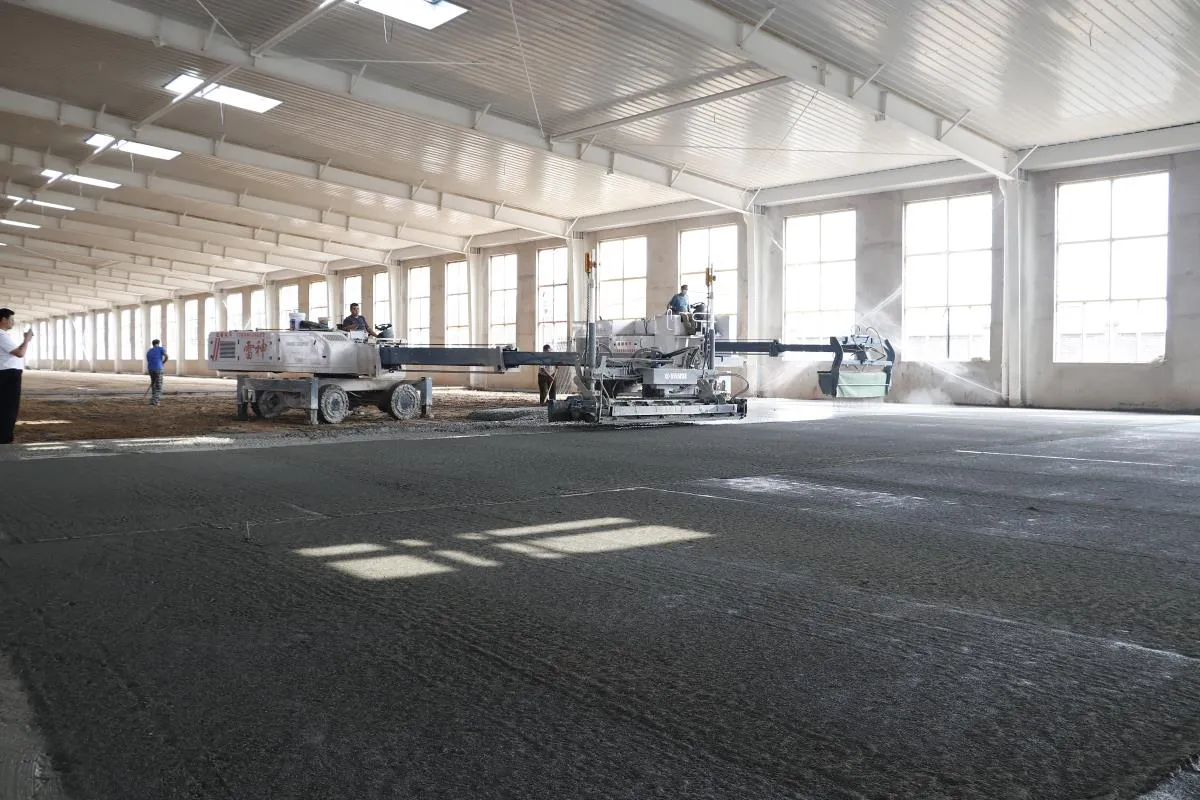
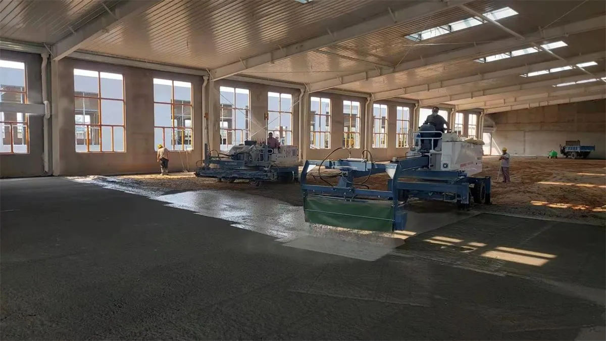
Thanks to All the Friends Who Support and Trust Shandong Vanse Machinery Technology Co., Ltd.
If you want to know more about Shandong Vanse Machinery Technology Co., Ltd. or have any questions, please feel free to contact us:
Our Factory
Shandong Vanse Machinery Technology Co., Ltd.








Share this article

About the Author: Shandong Vanse Machinery Technology Co., Ltd.
Shandong Vanse Machinery Technology Co., Ltd. is a high-tech manufacturer specializing in concrete construction machinery, including laser screeds and related equipment. The company integrates R&D, production, and global sales, with products exported to over 60 countries and widely used in infrastructure projects worldwide.
Previous Post
Next Post
Related Articles
You Might Also Like
Determining the initial setting time of concrete and mastering the optimal timing for power trowel operation
The determination of the initial setting time of concrete and the timing of the entry of the power trowel machine are the keys to ensuring that the floor is flat, solid and free of cracks. Below, I will elaborate in detail in two parts: one is how to determine the initial setting time of concrete, and the other is how to grasp the best time for the power trowel to enter the site for operation. Initial setting refers to a "critical point" at which concrete begins to transform from a plastic state to a solid state. At this point, the concrete loses its fluidity but has not yet acquired strength. According to the national standard "Standard Test Methods for Performance of Ordinary Concrete Mixtures", the initial setting time is scientifically determined by a penetration resistance meter. Method: Sift out the mortar from the concrete mixture and load it into a specific container. From the start of pouring, test with a penetration resistance meter at regular intervals (such as 30 minutes). The determination criterion: When the penetration resistance reaches 3.5 MPa, the corresponding time is the initial setting time. Applicable scenarios: Laboratories or major project sites, where precise data is required to guide construction. In actual construction, workers rely on simple and effective empirical methods: Acupressure method (the most classic) : Operation: Press the concrete surface firmly with your fingers (or feet). Judgment Too early: If the fingers can easily press down very deep and cement slurry overflows, it indicates that it is far from beginning to set. Close to initial setting: When pressed hard, only a clear fingerprint of 3-5 millimeters is left on the surface, but no cement slurry overflows. This is a very important signal. Initial condensation: It requires a great deal of force to leave a very shallow mark. Footprint method Operation: Construction workers stand on the concrete surface and observe the sinking of the footprints. Judgment Too early: Deep footprints, obvious subsidence, and cement slurry being squeezed out around. Close to initial setting: The depth of the footprints is relatively shallow (about 5mm), and the edges of the footprints are clear, with no obvious precipitation of slurry water. At this point, people can walk on it, but there is a slight sense of sinking. Scratch method Operation: Use a nail, screwdriver or power trowel to make a mark on the concrete surface. JudgmentToo early: The scratch will close quickly and be filled with cement slurry. Near initial setting: The scratch can maintain its shape, with the edge slightly raised and no longer closed. This is a strong indication that the first power trowel operation can begin. The entry and operation of the power trowel machine are not completed in one go, but are carried out in stages. Mistiming can lead to serious consequences: Entering the site too early: The concrete is too soft, and the machine will sink and stick to the slurry, damaging the concrete structure and causing the surface to peel and the strength to decrease. Entering the site too late: The concrete is already too hard, and the power trowel machine cannot effectively lift the slurry and smooth it out, which is time-consuming and laborious, and is prone to surface cracking. The best time and process for work The operation of a power trowel machine is usually divided into two key stages: Phase One: Initial smoothing (lifting the slurry and finishing the surface) Timing: The concrete is at or slightly above its initial setting point. Specific status When a person stands on it, the depth of the footprints is about 3 to 5 millimeters. By using the scratch method, the scratch can remain clear. When the power trowel blade is placed on it, it will not sink obviously. Assignment purpose: Press the aggregates (stones) slightly into the lower layer. Lift the surface cement slurry up. Carry out large-scale preliminary leveling. Key points of operation The operation is carried out using a disc (rubbing disc). The machine should not run too fast. It should move smoothly and slowly. Pay attention to overlapping areas that have been worked on to ensure no omissions. Phase Two: Fine grinding and polishing Timing: After the initial smoothing, when the moisture and luster on the concrete surface disappear and almost no footprints are left when stepped on (approximately 1-3 hours after the initial setting, depending on the environment). Specific status The color of the concrete surface begins to darken and become darker. There is a rough feeling when touched, but no hard or brittle sensation. At this point, the concrete has already possessed an initial load-bearing capacity. Assignment purpose: Eliminate the tiny scratches left by the disc operation. Further compact and smooth the surface to achieve the required flatness and smoothness. Seal the surface capillary pores to enhance wear resistance and impermeability. Key points of operation Remove the disc and use a blade (spatula) to carry out the operation. The rotational speed and moving speed of the machine can be appropriately increased. Cross-operation, multiple times of polishing, each time more meticulous than the previous one. Stage Description of concrete state Test method Operation of the power trowel machine Purpose Waiting period Soft, deep footprints, with bleeding Finger pressure/footprint method No entry allowed Let the concrete settle naturally and bleed water to evaporate Initial freezing point The footprints are 3 to 5mm deep, the scratches are clear, and there is no bleeding Finger pressure/scratch method Prepare to enter Determine the timing of the first operation First assignment Reach or slightly exceed the initial freezing point The same as above Install the disc and smooth it out at low speed Slurry extraction and initial leveling Fine grinding operation The surface water luster disappears, and the footprints are extremely shallow or non-existent Observe the color and footprints Replace the blade and polish at medium to high speed Compact, smooth surface, and seal Environmental factors influencing timing Temperature and wind speed: When the temperature is high and the wind is strong, water evaporation is fast, the initial setting time will be shortened, and all processes need to be advanced. Humidity: When the humidity is high, water evaporation is slow, and the initial setting time will be prolonged. Patience is required. The concrete mix ratio: The type of cement, water-cement ratio, and admixtures (such as retarders) all significantly affect the initial setting time. Final suggestion For important floor construction, "better late than early" is a safer principle. A little later, at most it will take more effort. However, entering the site too early will cause irreversible damage to the concrete structure. Skilled construction workers will dynamically adjust the entry and operation time of the power trowel machine through continuous observation and simple tests. Note: The parameters provided in this document are for reference only and are not mandatory. Due to differences in technical characteristics between different brands and models of laser levelers, please consult the manufacturer for a suitable solution before actual operation. This reference document assumes no responsibility for any issues arising from failure to follow the manufacturer's instructions.Cement Floor Cracks: Cause Analysis and Prevention
Cracks in cement floors (typically referring to cement concrete surfaces, such as indoor floors, outdoor plazas, and parking lots) not only affect appearance but can also reduce durability and even hinder functionality due to water seepage and debris accumulation. The following detailed analysis covers common crack symptoms, core causes, and targeted prevention and control measures to help accurately identify and effectively resolve the problem. The form, width, and distribution of cement floor cracks directly reflect their causes and can be categorized as follows: Crack Types Appearance Characteristics Common Locations Hazard Level Surface Cracks Cracks are short and thin (<0.1mm wide), forming an irregular network with no discernible depth, mostly concentrated in the surface layer (1-3mm deep). Large indoor floors and outdoor plazas Low (appearance only, no structural risk) Vertical/Horizontal Cracks Cracks are long (several to tens of meters long), straight, 0.1-0.5mm wide, and can penetrate the surface layer (5-10mm deep). Along the length/width of the floor, or along both sides of a partition joint Medium (easy to seep, accelerating surface degradation) Cracks at the Edges and Corners of Plates Cracks extend from the corners of the slab (such as the corners of a square floor) toward the center, forming an L-shaped or diagonal pattern, with a width of 0.2-0.8mm. At the joints of indoor and outdoor floor panels, near wall corners High (likely to cause edge peeling, affecting pedestrian safety) Through-Breaking Cracks Cracks extend through the entire cement surface layer (even penetrating the base layer), are >0.5mm wide, and are sometimes accompanied by slight ground subsidence or sanding. Highly loaded areas (such as parking lots and warehouses), and areas with uneven subgrades Extremely High (may cause floor damage and water accumulation, requiring urgent attention) The root cause of cement floor cracking is "internal stress in the surface layer exceeding its tensile strength." The sources of this stress are related to five key factors: material, base layer, construction, environment, and usage. The details are as follows: Improper material selection or proportioning directly leads to insufficient crack resistance in the surface layer: Incorrect cement selection: Using cement with a high heat of hydration (such as P.O. 42.5R rapid-hardening cement) to cast large surfaces releases a large amount of heat during hydration, raising the internal temperature of the surface layer. Contraction upon cooling creates "temperature stress," which can cause longitudinal and transverse cracks. Using expired cement (which has reduced strength) can also lead to insufficient tensile strength in the surface layer, making it more susceptible to cracking. Poor aggregate grading: If the fine aggregate (sand) is too fine (fineness modulus <2.3) or the mud content is too high (>3%), the cement requirement will increase (more cement paste is needed to coat the aggregate), leading to increased shrinkage of the surface layer. If the coarse aggregate (stone) is too small (<5mm) or missing, it will not form a "skeletal support," resulting in unrestrained shrinkage of the surface layer and prone to network cracking. If the water-cement ratio is too high: In pursuit of fluidity during construction, water usage is often blindly increased (water-cement ratio > 0.55). After the surface layer hardens, excess water evaporates, creating internal voids and reducing density. This significantly increases shrinkage (approximately 20% increase in shrinkage for every 0.1 increase in water-cement ratio), which can easily lead to surface cracking and edge cracking. Improper admixtures/admixtures: Failure to add or incorrect addition of admixtures (e.g., failure to add a retarder in summer, resulting in rapid initial setting of the surface layer and inability to grout after surface water evaporates; failure to add an antifreeze in winter, resulting in internal structural damage after freezing); and failure to add admixtures such as fly ash and mineral powder (key to reducing hydration heat and shrinkage) result in poor crack resistance in the surface layer. Cement floor surfaces rely on the stable support of a base layer (such as a lime soil base, crushed stone base, or concrete base). Base layer problems can directly affect the surface layer: Uneven base layer settlement: If the base layer is not compacted layer by layer during construction (e.g., a lime soil base with a compaction level less than 95%), or if there is a weak soil layer beneath the base layer (e.g., uncompacted backfill), the surface layer can experience partial subsidence during use, subjecting it to tensile stress and causing through-hole cracks or cracks at the edges and corners of the slabs. Uneven/contaminated base layer surface: The base layer surface has a height difference greater than 5mm (not leveled). The surface layer has uneven thickness after pouring, with thinner areas shrinking faster than thicker areas, creating "temperature differential stress." Oil and loose dust on the base layer surface have not been cleaned, resulting in insufficient adhesion between the surface layer and the base layer. After hardening, the two separate, and the surface layer shrinks independently, causing cracks. No isolation layer is provided for the base layer: When the base layer is concrete or a rigid material, without an insulating layer such as polyethylene film, the surface layer adheres too tightly to the base layer. During shrinkage, it is constrained by the base layer and cannot deform freely, causing cracks in areas of stress concentration (such as corners and joints). Construction operation is critical to crack control. Common mistakes include: Improper pouring and vibration: Failure to follow the "staged pouring, gradual progress" principle during pouring (e.g., large areas of ground are not divided into blocks, with individual blocks >20 m2), resulting in no channels for the surface layer to shrink as a whole; insufficient vibration during vibration (low density in some areas of the surface layer, insufficient tensile strength) or over-vibration (aggregate sinks, cement slurry floats, forming a "floating slurry layer" on the surface. After hardening, the floating slurry shrinks and cracks, known as crazing). Incorrect timing of surface calendering: Calendering too early (the surface layer has not yet set and the cement slurry has not yet developed strength) can easily cause sanding on the surface; calendering too late (the surface layer has already set and a crust has formed on the surface) can damage the surface structure, forming microcracks that later expand into cracks. Inadequate or improper sizing of the slurry: Large areas of flooring (single floor area >15 m2) are not provided with standardized expansion joints (spacing: ≤6 m vertically, ≤8 m horizontally). This lack of "stress relief" during surface shrinkage can lead to vertical/transverse cracks along weak areas (such as the center). Insufficient expansion joint depth (<1/3 of the surface layer thickness) or inadequate filler (such as asphalt mortar) can cause cracks to extend along both sides of the expansion joints. Untimely/inadequate curing: Failure to cover and cure the surface layer within 12 hours of pouring (e.g., exposure to direct sunlight in summer or wind in winter) allows surface moisture to evaporate rapidly, preventing internal moisture from being replenished. This results in "shrinkage stress" and causes surface cracking. Insufficient curing time (<7 days) prevents the surface layer from reaching its designed strength (typically ≥70% strength), leading to premature loading (e.g., pedestrians or vehicles), which can easily lead to corner cracks or through-hole cracks. Ambient temperature and humidity fluctuations can exacerbate stress in the surface layer and induce cracks: Severe Temperature Fluctuations: In summer, during daytime pouring (ambient temperature 35°C), the temperature drops sharply at night (15°C). The surface layer cools and contracts rapidly, while the interior cools and contracts slowly. This internal constraint creates "temperature stress" on the surface, leading to longitudinal, straight cracks. In winter, if the surface layer freezes before reaching its frost resistance (≥70% of design strength), the internal moisture freezes and expands, and upon thawing, the volume contracts, forming "freeze-thaw cracks" (mostly cracks at the edges and corners of the slabs, accompanied by surface spalling). Chronic and unstable humidity: In humid environments (such as bathrooms and underground garages), the surface layer absorbs moisture over time, softening the cement paste and reducing its tensile strength. In dry environments (such as heated rooms and warehouses in northern China), moisture from the surface layer continuously evaporates, accumulating shrinkage stress. The alternating effects of these two factors can easily lead to surface cracking or through-hole cracks. Improper load or maintenance during use can accelerate the development of cracks: Premature loading or overloading: Heavy objects (such as furniture and building materials) are piled on the surface before it reaches its design strength (28 days), or vehicles are driven on it (for example, a parking lot is opened to traffic without proper maintenance). This causes the surface to be subjected to loads exceeding its tensile strength, leading to through-cracks or cracks along the edges of the slabs. Lack of routine maintenance: Failure to promptly seal small cracks in the surface allows rainwater and oil to seep in, eroding the surface's internal structure. Furthermore, in winter, the water that seeps in freezes and expands, causing cracks to widen. Prolonged exposure to heavy loads (such as frequent forklift traffic in a warehouse) can lead to localized stress concentrations, causing longitudinal cracks. The core of prevention and control lies in "source control (materials + base layer), process control (construction), and post-maintenance (environment + use)." It is divided into two parts: "preventive measures" and "crack repair measures": Precise Material Selection: Prioritize cement with low hydration heat (such as P.O. 42.5 ordinary cement or slag Portland cement); use well-graded medium sand (fineness modulus 2.3-3.0, mud content ≤3%) and 5-10mm continuously graded crushed stone (mud content ≤1%) as aggregates; add Grade I fly ash (15%-20%) or mineral powder (20%-25%) to reduce hydration heat and shrinkage. Strictly control the water-cement ratio: The water-cement ratio should be ≤ 0.5 (for standard floors) and ≤ 0.45 (for impermeable floors). If necessary, add a retarding water reducer (at a dosage of 0.5%-1%) to maintain fluidity while reducing water consumption and minimizing shrinkage risk. Ensure the base layer is compacted and leveled: The base layer (lime soil/gravel) should be constructed in layers, with each layer ≤30cm thick and a compaction level ≥95% (tested using the knife ring method). The base layer surface should be leveled with cement mortar, with a height difference ≤3mm and cleaned (free of oil stains and loose dust). Apply a primer if necessary (to enhance adhesion between the surface layer and the base layer). Installing Isolation Layers and Expansion Joints: For rigid base layers (such as concrete), lay a 0.1mm thick polyethylene film isolation layer. For base layers >10m long, install expansion joints every 6-8m along the length (20mm wide and filled with asphalt hemp) to prevent base layer shrinkage from transferring to the surface layer. Scientific pouring and vibrating: For large floor areas, pour in blocks, with each block ≤15 m2 (rectangular blocks, aspect ratio ≤1.5). Leave 20 mm wide joints between blocks (the joint depth should be 1/3-1/2 the surface layer thickness). Vibrate with a flat vibrator (at a speed of 1-1.5 m/min) until the surface is free of bubbles and slurry. Avoid missed or over-vibration. Choose the right timing for calendering: Calender in three steps: ① Before initial setting (after the surface layer has absorbed water), smooth it with a wooden trowel; ② After initial setting (no visible finger marks remain), perform initial compaction with an iron trowel; ③ Before final setting (when the surface is nearly hardened), perform final compaction with an iron trowel to ensure a smooth surface without any marks. Strengthened maintenance management: Cover the surface with geotextile or plastic film (add a shade net in summer and a thermal blanket in winter) within 12 hours after pouring to keep the surface moist. Curing time for ordinary surfaces is ≥7 days, and for impermeable/load-bearing surfaces is ≥14 days. Pedestrians and vehicles are prohibited from entering during the curing period. Temperature Control: In summer, avoid pouring at noon (select morning and evening temperatures between 25-30°C). Cover the surface to maintain moisture. In winter, preheat the aggregate (≥5°C) before pouring, ensure the surface is at least 10°C before pouring, and maintain an ambient temperature of ≥5°C during curing (use heating if necessary). Usage and Management: The surface should be cured for 28 days before use. Premature stacking of heavy objects is prohibited. In areas such as parking lots and warehouses, limit vehicle/cargo weight to the designed load capacity to avoid local overloading. Regularly inspect the floor surface and seal any minor cracks with epoxy resin glue. If cracks have already appeared, first clean them (remove debris and dust, and flush with a high-pressure water gun), then repair them as follows: Crack Types: Repair methods Material Selection Key Points: Surface cracks Surface sealing method Epoxy sealer, cement-based penetrating crystallization coating (CCCW) Use a brush to evenly apply the glue/paint to the crack surface and a 5cm area on either side. Repeat 2-3 times. Cure for 24 hours. Vertical/horizontal cracks (width < 0.5mm) Low-pressure grouting method Cement slurry (water-cement ratio 0.45), epoxy slurry Drill an 8mm diameter hole (5mm deep) every 20cm along the crack. Insert a grouting tube and inject grout using a low-pressure pump (0.2-0.3MPa) until the grout overflows. Cure for 7 days. Cracks along edges and corners (width 0.2-0.8mm) Painting mortar filling method Polymer cement mortar (cement: sand: latex = 1:2:0.15) Chisel away the loose surface layer on both sides of the crack (5-10cm wide, 3-5mm deep). Clean and apply a primer. Fill with mortar and compact. Cure for 7 days. Through cracks (width > 0.5mm) Grouting + reinforcement method High-strength epoxy slurry, carbon fiber cloth First, fill the crack with high-pressure grouting (1.0-1.5MPa). Then, apply carbon fiber cloth (15cm wide, along the crack). Apply a topcoat. Cure for 14 days. The key to preventing and controlling cracks in cement floors is "prevention is better than cure": By optimizing the material mix (controlling the water-cement ratio and adding admixtures), stabilizing the base layer (compacting, leveling, and insulating layers), and standardizing construction (block-by-block pouring, timely maintenance, and appropriate gridding), stress can be reduced at the source. If cracks have already occurred, appropriate repair methods should be selected based on the crack morphology (width, depth, and location) to prevent further crack expansion. Paying attention to load control and regular maintenance during daily use can significantly extend the service life of cement floors. Note: The parameters provided in this document are for reference only and are not mandatory. Due to differences in technical characteristics between different brands and models of laser levelers, please consult the manufacturer for a suitable solution before actual operation. This reference document assumes no responsibility for any issues arising from failure to follow the manufacturer's instructions.What are the maintenance aspects of concrete laser leveling machine?
◆ Daily inspection Routine inspections are key to ensuring that your concrete laser leveling is working properly and extending its service life. After each day's work is completed, the following inspections should be carried out on the leveling machine: 1. Check the engine oil level and coolant level to ensure sufficient oil and water. 2. Check whether the screws of each component are loose, and tighten them in time if they are loose. 3. Check whether the cable is damaged and replace it immediately if it is damaged. 4. Check whether wearing parts such as scrapers and laser transmitters are seriously worn. If they are severely worn, replace them in time. ◆ Regular cleaning Regular cleaning of the concrete laser leveling can prevent dirt and debris from causing damage to the equipment and improve the efficiency of the equipment. The leveling machine should be thoroughly cleaned once a week. Key cleaning areas include: 1. Engine: Use professional engine cleaner to clean to remove carbon deposits and sludge. 2. Laser transmitter: Wipe it with alcohol cotton to remove dust and fingerprints. 3. Scraper: Polish with sandpaper or replace with a new scraper 4. Cable: Wipe with dry cloth and keep dry ◆ Lubrication system The lubrication system of a concrete laser leveling is vital to the normal operation of the equipment. Equipment should be lubricated regularly. The lubrication parts include: 1. Use professional engine lubricating oil for the engine crankshaft, connecting rod and other parts. 2. Use professional grease for each bearing, chain and other parts 3. Regularly check whether there is any leakage in the lubrication system, and deal with it promptly if there is any leakage. ◆ Battery and charger The battery and charger of the compact soil laser leveler are the energy supply system of the equipment and require special attention and maintenance. Batteries and chargers should be checked regularly for the following: 1. Check the battery power and charge it in time if the power is insufficient. 2. Check whether the charger is working properly. If there is any problem, repair or replace it in time. 3. When the device is not used for a long time, the battery should be removed, stored separately and charged regularly to prevent battery damage. 4. Avoid using the battery at too high or too low temperature to prevent the battery from overheating or freezing. 5. Avoid over-discharging or charging the battery to prevent shortening of battery life. ◆ Replacement of wearing parts Some parts of the compact soil laser leveling machine are wearing parts and need to be replaced regularly to ensure the normal operation of the equipment and extend its service life. These wearing parts include: 1. Scraper: Replace regularly according to the degree of wear. It is recommended to replace it every 50 hours of work. 2. Filter: Replace regularly according to working conditions. It is generally recommended to replace it every 200 working hours. 3. Cable: If damaged, it should be replaced in time. It is generally recommended to replace it once a year. 4. Seals: If there are signs of aging, oil leakage, etc., they should be replaced in time. 5. Replacement of wearing parts should be carried out in accordance with the equipment manufacturer's recommendations, and original accessories should be used to ensure equipment performance and safety. ◆ Safety inspection Safety inspection is an important part of the maintenance of concrete laser leveling machine, which can ensure that the equipment will not cause accidents during work. The following safety checks should be performed on the equipment regularly: 1. Check whether the screws of each component are loose, especially the screws of the engine and important components. 2. Check whether the cable is damaged to prevent electric shock accidents. 3. Check the equipment for oil leakage to prevent fire accidents. 4. Check whether the lights and alarms of the equipment are working properly and ensure that the equipment can send out warning signals in time during work. 5. Check whether the emergency stop button of the equipment is working properly to ensure that the equipment can be stopped immediately in an emergency. 6. When conducting safety inspections, the equipment manufacturer's safety operating procedures and precautions should be followed to ensure the safety of the inspection process. If safety hazards are discovered, they should be dealt with promptly to prevent accidents.