Technical Knowledge
How should the slump of concrete pavement construction be adjusted in different construction scenarios?

In concrete pavement construction, the adjustment of slump needs to be carried out according to the characteristics of different construction scenarios. The following are some adjustment methods for common construction scenarios
High temperature environment:
Reason:
The increase in temperature will accelerate the cement hydration rate and the water evaporation rate, resulting in faster loss of concrete slump and reduced fluidity.
Adjustment method:
Appropriately increase the slump. It is generally recommended to increase it by 2040mm compared with normal temperature construction. For example, the slump is controlled at 80100mm at normal temperature, and it can be adjusted to 100140mm at high temperature. At the same time, measures can be taken to reduce the temperature of raw materials, such as shading aggregates, spraying water to cool down, using underground cold water to mix concrete, and adding ice cubes to the mixing water to control the concrete outlet temperature ≤30℃.
Low temperature environment:
Reason:
Low temperature will prolong the setting time of concrete and deteriorate the construction performance. If the slump is too small, the concrete may be difficult to vibrate and compact.
Adjustment method:
The slump should not be too large, usually controlled at 3060mm. Warm water can be used to mix concrete to increase the temperature of the concrete out of the machine, and the amount of admixture can be appropriately reduced to avoid too long setting time of the concrete. In addition, attention should be paid to the insulation and maintenance of the concrete to prevent freezing.
Longdistance transportation:
Reason:
Long transportation time will cause the slump of concrete to be lost. If the initial slump is small, it may be difficult to meet the construction requirements when arriving at the construction site.
Adjustment method:
Appropriately increase the slump when setting off, such as increasing it by 2030mm compared to normal construction. For example, the normal construction slump is 80100mm, and it can be set to 100130mm during longdistance transportation. At the same time, on the basis of the continuous lowspeed rotation of the mixer tank (24 rpm), a transport retarder can be added to ensure that the slump loss rate is ≤30% within 2 hours.
Pumping construction:
Reason:
Pumping requires concrete to have good fluidity and pumpability to pass through the pipeline smoothly and reach the pouring location.
Adjustment method:
The slump is usually controlled at 120180mm. It is necessary to select a suitable pumping agent and adjust its dosage according to the pumping distance, height and pipeline layout. At the same time, optimize the concrete mix ratio and control the sand ratio at around 35%45% to improve the fluidity and water retention of the concrete.
Nonpumping construction:
Reason:
If manual paving or small mechanical paving is used, the concrete does not need to have high fluidity like pumping, but it still needs to have a certain workability to facilitate paving and vibration.
Adjustment method:
The slump is generally controlled at 3080mm. If the slump is increased by one level (i.e., by 20 30 mm), in addition to increasing the sand content by more than 1% to ensure stability and workability, the amount of water (5 10 kg/m3) and cement (10 kg per cubic meter) must be increased accordingly.
In actual construction, the optimal slump and mix ratio should be determined through tests according to specific conditions, and inspection and adjustment should be carried out strictly in accordance with relevant standards and specifications to ensure the construction quality of the concrete pavement.
Thanks to All the Friends Who Support and Trust Shandong Vanse Machinery Technology Co., Ltd.
If you want to know more about Shandong Vanse Machinery Technology Co., Ltd. or have any questions, please feel free to contact us:
Our Factory
Shandong Vanse Machinery Technology Co., Ltd.








Share this article

About the Author: Shandong Vanse Machinery Technology Co., Ltd.
Shandong Vanse Machinery Technology Co., Ltd. is a high-tech manufacturer specializing in concrete construction machinery, including laser screeds and related equipment. The company integrates R&D, production, and global sales, with products exported to over 60 countries and widely used in infrastructure projects worldwide.
Previous Post
Next Post
Related Articles
You Might Also Like
Establishment and sharing of a troubleshooting manual for common faults of concrete laser leveling
This is a detailed plan on how to establish and share the "Common Fault Troubleshooting Manual for concrete laser leveling". It not only contains the core content framework of the manual, but also provides a full-process approach for establishing, maintaining and sharing this knowledge system. Concrete laser leveling machines are core equipment in modern floor construction, and their operational status directly affects the construction efficiency and floor quality. The establishment of a standardized troubleshooting manual aims to: Enhance efficiency: Quickly locate and resolve faults to minimize downtime. Cost reduction: Avoid major repairs due to minor malfunctions and reduce reliance on senior technicians. Unified standards: Provide a unified troubleshooting process and solutions for both new and experienced operators as well as mechanics to reduce operational errors. Knowledge inheritance: Transform the experience of master craftsmen into replicable and shareable organizational assets. Ensure safety: Standardize operations to prevent safety accidents caused by improper maintenance. (1) Core Content Framework of the manual The manual should adopt a clear, concise and easy-to-query structure. The suggested list is as follows: Cover Equipment name and model Manual version number, formulation/revision date Establish departments/personnel Part One: Safety First General Safety Regulations: All maintenance and inspection work must be carried out after power failure and pressure relief. Personal protective equipment (PPE) requirements: safety helmets, protective glasses, gloves, steel-toed shoes, etc. Safety checklist before operation: such as checking the surrounding environment of the equipment, the effectiveness of the emergency stop button, etc. Part Two: Introduction to Equipment Foundation and Working Principle Diagram of the main components of the entire machine (chassis, scraper, vibrator, laser receiver, hydraulic system, control system, etc.). A brief description of the working principle of the laser elevation control system. A brief description of the principle of hydraulic transmission. Part Three: Quick Troubleshooting Table for Common Faults (Core Part) It is recommended to use a table format, which is clear at a glance. Fault phenomenon Possible reasons Troubleshooting steps Solution Risk Warning/Remarks 1. The leveling accuracy is inaccurate The elevation remains persistently high or low 1. The elevation setting of the laser emitter is incorrect 1. Recheck the elevation of the laser emitter 1. Reset the laser elevation Before calibration, ensure that the ground is stable and the laser signal is unobstructed 2. The initial height of the laser receiver was not calibrated 2. Execute the "centering" calibration procedure for the receiver 2. Re-calibrate the receiver 3. Wear of the machine's reference surface 3. Check the wear condition of the scraper base plate 3. Replace or adjust the scraper base plate The ground shows waves or unevenness 1. The machine's walking speed is unstable 1. Check the walking motor and control system 1. Adjust to a uniform walking speed 2. Pressure fluctuations in the hydraulic system 2. Check the hydraulic oil level, filter element and pump valve 2. Replace the hydraulic oil or filter element and inspect the hydraulic components 3. The ground base is soft and uneven 3. Assess the compaction degree of the base layer 3. Handle the grassroots level 2. Vibration system failure The vibrator is not working or is weak 1. Power supply/circuit failure of the vibrator Check the fuses, circuits and switches 1. Replace the fuse and repair the circuit When repairing the circuit, be sure to cut off the power 2. The vibration motor is damaged 2. Measure the resistance of the motor 2. Replace the vibration motor 3. Blockage or insufficient pressure in the hydraulic oil circuit 3. Detect the hydraulic pressure of the vibration circuit 3. Clean the filter screen and adjust the relief valve 3. Malfunction of the walking system – Walk on one side or not at all 1. The walking track is stuck 1. Clear the debris inside the tracks 1. Clear out debris Do not force the drive to avoid damaging the components 2. Malfunction of the walking motor 2. Check the working pressure of the motor 2. Inspect or replace the motor 3. The control solenoid valve gets stuck 3. Tap or clean the solenoid valve 3. Replace the solenoid valve 4. Hydraulic system failure The system is noisy and the oil temperature is high 1. The hydraulic oil level is too low or the oil quality is incorrect 1. Check the oil level and the type of oil 1. Add or replace standard hydraulic oil Be careful not to get burned when checking the oil level while warming up the machine 2. Air enters the hydraulic pump or it is damaged 2. Exhaust and listen to the sound of the pump running 2. Tighten the oil suction pipe and replace the oil pump 3. The hydraulic oil filter element is clogged 3. Check the filter element clogging indicator 3. Replace the filter element 5. Laser system failure The receiver signal is unstable 1. The laser signal is blocked 1. Check the laser path 1. Clear the obstacles 2. The receiver sensor is dirty 2. Clean the receiver panel 2. Wipe with a soft cloth 3. Environmental disturbances (strong light, vibration) 3. Avoid interference sources 3. Adjust the position of the equipment or add a light shield Part Four: Regular Maintenance and Upkeep Plan Daily maintenance: Cleaning, checking the oil level, and inspecting the fasteners. Weekly/monthly maintenance: Replace the filter element, check the wear of the tracks, and calibrate the laser system. Quarterly/annual maintenance: Replace hydraulic oil and conduct a comprehensive inspection of key components. Part Five: Appendix Key component model table: such as hydraulic oil model, filter element model, fuse specification, etc. Service contact information: Phone numbers of the equipment manufacturer, internal maintenance supervisor, and external service engineer. Fault record sheet: It is used by operators to record the detailed situation of each fault for subsequent optimization of the manual. (2) Manual Compilation Process Establish a project team: Led by the equipment manager, the team members include: senior operators, maintenance technicians, and technical document clerks. Information collection Refer to the official "Operation and Maintenance Manual" for all the equipment. On-site interview: In-depth interviews with experienced operators and maintenance workers, documenting the "classic malfunctions" and "folk tricks" they encountered. Historical data analysis: Analyze previous maintenance record sheets to identify high-frequency fault points. Content writing and visualization The technical document clerk writes the first draft based on the collected information in accordance with the above framework. Use a lot of pictures and ICONS! In the "Possible Causes" and "Solutions" sections, attach physical photos or simple sketches as much as possible, such as "This is the filter element that needs cleaning" or "This is the location of the calibration button". Review and Verification Distribute the first draft to all operators and maintenance workers for trial use and review. Make revisions based on feedback to ensure the content is accurate and the language is easy to understand. Finalization and release: The final version of the manual (V1.0) is formed and enters the sharing process. (1) Sharing form Physical manual Make waterproof, oil-proof and durable loose-leaf manuals and place them in the cab or toolbox of each piece of equipment. Advantages: Readily available on site and does not rely on electronic devices. Disadvantages: Inconvenient to update, prone to damage or loss. Digital Manual PDF electronic version: Distributed to each employee's wechat, email or company shared disk for easy access at any time on mobile phones or computers. Enterprise internal APP/ microsite: Transform the manual content into a simple web page or embed it into the company's OA/ERP system, supporting keyword search for the best user experience. Qr code: Paste a QR code in a prominent position on each device. Scan the code to view the latest version of the electronic manual. This is a highly recommended way! (2) Management and Update Mechanism The manual is not set in stone and a dynamic update mechanism must be established. Designated person in charge: Clearly define the maintenance person in charge of the manual (usually the equipment supervisor). Establish feedback channels: Encourage all users to provide feedback on new faults or better solutions not covered in the manual in the "Fault Record Sheet" or through the wechat work group. Regular review: Every six months or once a year, the project team conducts a centralized review of the manual and updates it based on feedback and technological development. Version control: Each update requires the version number and date to be updated, and everyone should be notified through group announcements, emails, etc., to ensure that everyone is using the latest version. For physical manuals, it is necessary to collect the old versions in a timely manner and replace them with new ones. The value of a manual lies in its use. Formal kick-off meeting: Organize a brief meeting to introduce the purpose, content and access methods of the manual to all employees. Practical training: Use the manual as an essential textbook for new employees' onboarding training and conduct troubleshooting drills in combination with real equipment. Case Sharing Session: Every month, during the safety meeting or morning meeting, an operator is invited to share a case of successfully resolving a fault using the manual, and a small reward is given to stimulate enthusiasm for use. By systematically establishing a detailed and illustrated troubleshooting manual, and adopting a shared approach that combines online and offline methods, supplemented by effective management and training, this "Common Fault Troubleshooting Manual for Concrete Laser leveling Machines" is bound to transform from a mere document into a core asset that enhances team combat effectiveness and ensures equipment availability. Note: The parameters provided in this document are for reference only and are not mandatory. Due to differences in technical characteristics between different brands and models of laser levelers, please consult the manufacturer for a suitable solution before actual operation. This reference document assumes no responsibility for any issues arising from failure to follow the manufacturer's instructions.Can concrete polishing machines replace power trowels for achieving mirror-finish super flat floors?
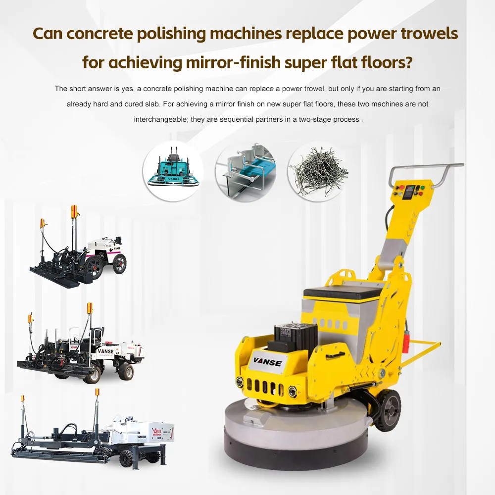
The short answer is yes, a concrete polishing machine can replace a power trowel, but only if you are starting from an already hard and cured slab. For achieving a mirror finish on new super flat floors, these two machines are not interchangeable; they are sequential partners in a two-stage process . To understand why, you have to look at when in the concrete's life cycle each machine operates. A power trowel works on wet, setting concrete, while a polishing machine works on hard, cured concrete. Feature Power Trowel (Finishing Stage) Concrete Polisher (Hardening Stage) When to Use During the concrete's initial set (while still plastic/hardening) . After the concrete has fully cured (typically 28+ days) . How it Works Uses steel blades to float, compact, and "burnish" the surface paste, creating a temporary mechanical shine . Uses abrasive diamond pads to physically grind down the surface, exposing the aggregate and creating a permanent structural shine . Result Creates the initial dense, smooth surface required before any polishing can happen. This is the foundation. Removes the top layer to achieve the final desired gloss level (from satin to mirror). This is the final art. Goal Densification & Profile Creation. To prepare a flat, cured slab ready for polishing. Aesthetics & Durability. To reveal the aggregate and create a long-lasting, high-gloss finish . Think of it like building a piece of fine furniture. You cannot start with a rough log and immediately apply varnish. You need a plane to make it flat first. The power trowel's job is to create a perfectly flat and dense foundation. As we discussed in your previous question about operation time, the trowel burnishes the surface. If you try to use a polishing machine on a floor that hasn't been properly power-troweled, the slab will be too rough and uneven. The polisher would have to remove far too much material to achieve flatness, which is inefficient and costly . Once the concrete is cured, the polishing machine takes over. You attach diamond abrasive pads (starting coarse and moving to very fine, like 3,000 grit) . This process physically cuts the surface, revealing the inner beauty of the stone and creating a shine that is part of the material itself, not just a surface effect . Technically, yes, a power trowel can be converted into a high-speed polishing machine, but this is for the polishing phase only. The Conversion: You can buy a conversion kit (planetary grinding heads) that attaches to the bottom of a power trowel, allowing it to hold diamond polishing pads . The Advantage: This is incredibly fast. A converted ride-on power trowel can polish over 10,000 square feet a day, making it ideal for massive warehouses . The Trade-off: A converted trowel is less precise than a dedicated planetary grinder and cannot get close to walls or into corners. You would still need a smaller, walk-behind grinder for the edges . Regardless of which machine you use for polishing, you must apply a chemical hardener called a densifier (usually lithium silicate) after the initial grinding passes . This chemical reacts with the concrete to make it rock-hard, allowing it to accept a high-gloss polish. Without it, the surface will remain chalky and dull. In short: Use the power trowel to build the perfect canvas. Then, bring in the polisher to create the artwork. If you are planning a project, knowing the desired final gloss level (e.g., matte, satin, or high-gloss mirror) will help determine exactly which grit progression you need for the polishing phase. Let me know if you'd like more details on that. Contact us NOW Note: The parameters provided in this document are for reference only and are not mandatory. Due to differences in technical characteristics between different brands and models of laser levelers, please consult the manufacturer for a suitable solution before actual operation. This reference document assumes no responsibility for any issues arising from failure to follow the manufacturer's instructions.How does the concrete laser leveling machine improve construction efficiency and quality?
Concrete laser leveling machine is a key equipment to improve efficiency and quality in modern concrete construction. Its core is to achieve high-precision leveling through the laser system, and to complete large-area concrete paving, vibration and leveling in combination with mechanical structure. The following is a detailed analysis of its advantages and mechanism of action from the two aspects of construction efficiency and construction quality: Traditional manual leveling requires multiple vibration and scraping in different areas, and is limited by manual physical strength and operating range (small single-person operation area). The laser leveling machine can cover a range of up to 3-6 meters (depending on the model) through a mechanical arm or scraper, and can achieve a construction area of 500-3000㎡/day (traditional manual only 100-300㎡/day), especially suitable for large areas such as factories, warehouses, and parking lots. – Advantages: Reduce the gap between manual shifts and tool adjustments, and realize the integrated continuous operation of "paving-vibration-leveling". The laser leveling machine establishes a horizontal reference plane through a laser transmitter, and the sensor receives signals in real time and automatically adjusts the scraper height, without the need for repeated manual measurement and adjustment. For example: – Traditional manual work requires frequent calibration of elevations with rulers and levels, measuring every 1-2 meters; the laser system can dynamically level in real time, with a response time of only 0.1-0.3 seconds, greatly reducing the time spent on measurement and adjustment. The bottom of the equipment is usually equipped with multiple sets of high-frequency vibrating rods (vibration frequency 200-300 times/minute), which complete the concrete vibration and compaction while leveling, avoiding the repeated process of manual vibration first and then leveling. The vibration depth can reach 10-30cm, the coverage range is synchronized with the leveling, and the efficiency is 3-5 times higher than manual vibration alone. The horizontal accuracy of the laser system can reach ±1mm/3m, which is much higher than the ±5-10mm error of manual leveling. The principle is: – The laser transmitter emits a 360° rotating laser beam to form a horizontal reference plane; – The fuselage sensor detects the height difference with the reference plane in real time, and automatically adjusts the scraper height through the hydraulic system to ensure that the surface flatness of the concrete meets high standards (such as precision workshops, airport runways, etc.). When paving manually, coarse aggregates are prone to sinking (segregation) due to uneven shovel throwing and vibration. The laser leveler pushes concrete at a uniform speed through the scraper, and cooperates with high-frequency vibration to make the aggregate distribution more uniform, avoiding defects such as honeycombs and hemp surfaces. At the same time, the vibration frequency can be adjusted according to the slump of the concrete (such as reducing the frequency when the slump is high to prevent over-vibration segregation), and it is more adaptable. Manual leveling is greatly affected by experience, physical strength, and environment (such as strong light and fatigue), and height differences may occur in the same area; laser leveling machines use mechanical automation to ensure the consistency of bid height and slope (supporting one-way/two-way slope settings) in large-scale construction, especially suitable for sites with drainage slope requirements (such as parking lots and roofs). Due to the high surface flatness and uniform density, there is no need for repeated finishing before the initial setting of concrete, and the maintenance stage can be quickly entered, indirectly reducing the quality risks caused by later repairs. The laser leveling machine reduces the inefficient links of manual intervention (such as multiple measurements and repeated vibration) through "automatic benchmark control + integrated process integration", and avoids the quality fluctuations of manual operation through high-precision systems. In actual application, its comprehensive benefits are reflected in: – Efficiency: Construction speed increased by 2-3 times, and labor costs reduced by more than 50%; – Quality: The flatness pass rate increased from 70%-80% of manual work to more than 95%, and the problems of cracking and sanding in the later stage of the ground were reduced by more than 60%. Therefore, in large-scale, high-standard concrete construction, laser leveling machines have become the core equipment to replace traditional processes. Click the below to jump immediately!!! AMOUR JOINT CONCRETE LEVELING MACHINE LIGHT TOWER POWER TROWEL SLIPFORM MACHINE STEEL FIBER TOPPING SPREADER TRACKED MINI DUMPER