Technical Knowledge
What are the special operating techniques of laser leveling machines in different construction environments?

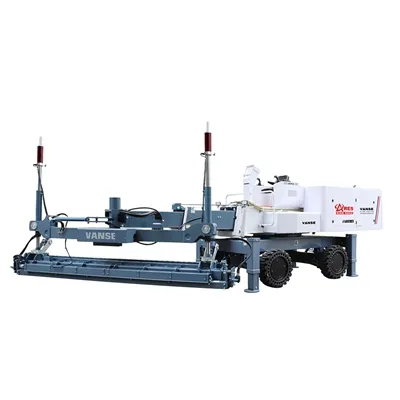
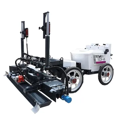
Laser leveling machine is a kind of equipment used for large-area concrete paving and leveling. There are special operating skills in different construction environments:
Indoor floor construction
1. **Space limitation coping skills**
– Indoor space is usually limited, and the size of laser leveling machine is relatively large. Before entering the indoor construction site, accurately measure the size of doors, passages, etc. to ensure that the machine can enter smoothly. If the passage is narrow, some parts, such as detachable scrapers, may need to be removed and installed after the machine enters the room.
– During operation, pay attention to the turning radius of the machine due to limited indoor space. Plan the leveling route in advance and minimize the machine's large-scale turning movements to avoid colliding with walls, columns and other building structures.
2. **Dust control skills**
– Pay special attention to dust control during indoor construction, because dust will affect indoor air quality and subsequent decoration processes. The laser leveling machine can be equipped with an efficient dust suction device to simultaneously remove dust during the leveling process.
– For situations where there are more loose debris on the ground, use a broom or industrial vacuum cleaner for preliminary cleaning before construction to reduce the situation of debris being raised during the leveling process.
3. **Skills for flatness accuracy control**
– Indoor floors usually have high requirements for flatness, such as warehouse floors, exhibition hall floors, etc. Before construction, carefully calibrate the laser transmitter and receiver to ensure the accuracy of the laser signal.
– According to the designed slope of the indoor floor (if any), accurately set the control system parameters of the laser leveler. For example, for indoor floors with drainage requirements, the leveling operation should be carried out according to the designed drainage slope (such as 0.3% – 0.5%), and the flatness should be checked regularly during the construction process. Tools such as rulers can be used for random inspections.
Outdoor large-area site construction (such as squares and parking lots)
1. **Skills for dealing with complex terrain**
– If there is an uneven original ground on the construction site, such as potholes, bumps, etc. Before construction, use equipment such as bulldozers to perform preliminary leveling on the site and deal with areas with large height differences. For small potholes, the thickness of the concrete can be appropriately increased during the construction of the laser leveler to fill them.
– When the site has a certain slope, the working mode of the laser leveler should be adjusted according to the design requirements. For example, for the gentle slopes at the entrance and exit of the parking lot, they should be leveled according to the specified slope (such as no more than 7% – 10%), and the transition with the adjacent plane area should be natural and smooth.
2. **Tips for adapting to weather changes**
– Weather factors have a greater impact on outdoor construction. If high temperatures are encountered, the solidification speed of concrete will be accelerated. The leveling construction speed should be appropriately accelerated, and retarders can be added to the concrete to extend the working time of the concrete. At the same time, attention should be paid to providing heatstroke prevention measures for operators.
– When encountering rainy weather, the laid but not completely solidified concrete should be covered with plastic film in time to prevent rain erosion. If there is water accumulation on the ground, drain it before construction, and check the water content of the ground to avoid affecting the quality of concrete due to excessive water content.
3. **Tips for improving construction efficiency**
– For large outdoor sites, in order to improve construction efficiency, multiple laser leveling machines can be used for collaborative operation. When dividing the construction area, the walking route of the machine should be reasonably planned to avoid mutual interference.
– Arrange the supply of concrete in advance to ensure that concrete can be supplied to the construction area continuously and stably. Concrete mixer trucks can be used to unload directly near the construction area to reduce the concrete transportation time and improve the overall construction progress.
Construction on narrow roads or corridors
1. **Machine positioning skills**
– When constructing on narrow roads or corridors, the positioning of the laser leveler must be accurately controlled. Due to the narrow space, the machine may not be able to perform regular steering operations. The concrete can be spread and leveled by adjusting the angle of the scraper by alternating forward and backward movements.
– Set up warning signs on both sides of the road or corridor in advance to prevent other vehicles or personnel from interfering with the construction, and also to avoid the machine from colliding with roadside facilities.
2. **Safety assurance skills**
– When constructing in narrow spaces, the safety of the operator is of vital importance. The operator should wear protective equipment, such as a helmet, reflective vest, etc. And ensure that the machine's emergency brake is in good condition so that it can stop in time in case of an emergency.
– As roads or corridors may have a certain amount of traffic flow, during construction, it is necessary to work closely with on-site traffic management personnel and select periods with less traffic flow for construction, or adopt temporary traffic control measures.
Thanks to All the Friends Who Support and Trust Shandong Vanse Machinery Technology Co., Ltd.
If you want to know more about Shandong Vanse Machinery Technology Co., Ltd. or have any questions, please feel free to contact us:
Our Factory
Shandong Vanse Machinery Technology Co., Ltd.








Share this article

About the Author: Shandong Vanse Machinery Technology Co., Ltd.
Shandong Vanse Machinery Technology Co., Ltd. is a high-tech manufacturer specializing in concrete construction machinery, including laser screeds and related equipment. The company integrates R&D, production, and global sales, with products exported to over 60 countries and widely used in infrastructure projects worldwide.
Previous Post
Next Post
Related Articles
You Might Also Like
Technical difficulties and solutions in concrete floor construction
Technical difficulties and solutions in concrete floor construction With the continuous advancement of modernization, concrete floors have been widely used in various construction projects. Concrete floor construction not only requires high strength and stability, but also needs to meet the requirements of beauty and durability. However, in the construction process of concrete floors, many technical difficulties are often encountered. If these difficulties are not handled properly, they will directly affect the quality and use effect of the floor. Therefore, this article will conduct an in-depth discussion on the technical difficulties and corresponding solutions in concrete floor construction, in order to provide a useful reference for actual construction. 1. Material selection and proportioning issues The material selection and proportioning of concrete floors are the primary links in construction, which are directly related to the strength, durability and beauty of the floor. In actual construction, floor quality problems often occur due to improper material selection or unreasonable proportioning. Technical difficulties: ☑ Unstable material quality affects the performance of concrete. ☑ Unreasonable proportioning design leads to insufficient strength or cracking of concrete. Solution: ☑ Select high-quality materials: Ensure that the quality of raw materials such as cement, aggregates, additives, etc. is stable and meets construction requirements. ☑ Reasonable design of the proportion: According to the project requirements and material properties, scientific proportion design is carried out to ensure the strength, durability and working performance of the concrete. 2. Construction preparation and base treatment Construction preparation and base treatment are important prerequisites for concrete floor construction, and are crucial to ensuring the quality of the floor. If the construction preparation is not sufficient or the base treatment is not in place, the flatness and adhesion of the floor will be seriously affected. Technical difficulties: ☑ Poor construction environment affects the construction effect. ☑ Inadequate base treatment causes cracking or hollowing of the floor. Solution: ☑ Fully prepare the construction environment: Ensure that the construction site is dry and clean, without stagnant water, oil and other debris, to provide good conditions for construction. ☑ Strictly handle the base: Thoroughly clean and polish the base to ensure that there is no floating dust, oil, etc. At the same time, check the strength and flatness of the base, and reinforce or repair the base that does not meet the requirements. 3. Concrete pouring and vibration Concrete pouring and vibration are key links in concrete floor construction, which directly affect the density and strength of the floor. If the pouring is uneven or the vibration is not in place, it will cause quality problems such as honeycombs and rough surfaces on the floor. Technical difficulties: ☑ Uneven concrete pouring, resulting in thickness differences. ☑ Insufficient or excessive vibration affects the density of concrete. Solution: ☑ Evenly pour concrete: Use appropriate pouring methods to ensure that the concrete is poured evenly and continuously on the base to avoid thickness differences ☑ Reasonably control vibration: According to the slump of concrete and construction requirements, select appropriate vibration equipment and methods to ensure that the concrete is vibrated and dense, and avoid excessive vibration that causes concrete segregation. 4. Surface flatness and aesthetics The surface flatness and aesthetics of concrete floors are important indicators for measuring construction quality. If not handled properly, it will lead to problems such as uneven floor surface and uneven color. Technical difficulties: ☑ Surface flatness is difficult to control, resulting in height differences ☑ Poor aesthetics, uneven color or stains Solution: ☑ Control surface flatness: Use appropriate scraping tools and methods to finely handle the concrete surface to ensure that the surface is flat and smooth. At the same time, pay attention to controlling the fluidity and slump of concrete during pouring to avoid height differences. ☑ Improve aesthetics: Choose appropriate pigments and additives to make the concrete surface present a uniform color and texture. For stains or color differences that have already appeared, grinding, repairing and other methods can be used to deal with them. 5. Construction joint treatment and maintenance Concrete floors will inevitably produce construction joints during construction. If not handled properly, the floor will crack or affect the overall appearance. At the same time, maintenance is also an important part of ensuring the quality of the floor. Technical difficulties: ☑ Improper construction joint treatment leads to floor cracking. ☑ Inadequate maintenance affects the strength and durability of the floor Solution: ☑ Reasonable treatment of construction joints: Set force transmission rods at the construction joints or take other effective measures to ensure that the connection at the construction joints is firm and flat. At the same time, strengthen vibration and compaction on both sides of the construction joints to avoid voids or cracks. ☑ Strengthen maintenance management: Develop a reasonable maintenance plan based on construction requirements and climatic conditions. Keep the floor surface warm during maintenance, avoid direct sunlight and wind and rain erosion. For cracking or peeling problems, handle and repair them in time. 6. Quality monitoring and problem troubleshooting Quality monitoring and problem troubleshooting are key links to ensure the quality of concrete floor construction. Through monitoring and troubleshooting, problems in the construction process can be discovered and handled in a timely manner to ensure that the floor quality meets the design requirements. Technical difficulties: ☑ Insufficient quality monitoring means make it difficult to fully control quality. ☑ Untimely or inaccurate problem troubleshooting leads to quality risks. Solution: ☑ Improve the quality monitoring system: Establish a sound quality monitoring system and methods to comprehensively monitor and record the raw materials, construction process, and finished product quality of concrete. Use advanced testing equipment and instruments to improve the accuracy and reliability of monitoring. ☑ Strengthen problem investigation; regularly patrol and inspect the construction site, focusing on construction joints, corners and other parts prone to problems. Once quality problems or hidden dangers are found, immediately organize relevant personnel to investigate and deal with them to ensure that the problems are solved in a timely manner. At the same time, establish a quality problem record and feedback mechanism, track and evaluate the treatment process, and continuously improve the quality management system. 7. Implementation of safety and environmental protection measures In the process of concrete floor construction, the implementation of safety and environmental protection measures is equally important. This is related to the life safety and physical health of construction workers, as well as environmental protection and sustainable development. Technical difficulties: ☑ There are many safety hazards at the construction site, and management is difficult. ☑ Pollution problems such as noise and dust during construction are difficult to effectively control. Solution: ☑ Strengthen safety management: formulate strict construction safety management system and operating procedures to ensure that construction personnel abide by relevant regulations. Conduct regular safety inspections on the construction site to promptly discover and rectify safety hazards. At the same time, provide necessary safety protection equipment and supplies to ensure the safety of construction personnel. ☑ Implement environmental protection measures: Take effective dust reduction and noise reduction measures during the construction process to reduce the impact of construction on the surrounding environment. Reasonably handle construction wastewater and waste to avoid pollution of soil and water sources. Promote the use of environmentally friendly materials and construction technologies to reduce energy consumption and emissions during construction. In summary, the technical difficulties and solutions in concrete floor construction involve many aspects. In the actual construction process, it is necessary to formulate appropriate construction methods and measures according to specific circumstances, and at the same time strengthen quality monitoring and safety management to ensure that construction quality and safety and environmental protection meet the requirements. By constantly summarizing experience and lessons and optimizing construction techniques and methods, the quality of concrete floors can be improved. The efficiency and quality level of construction contribute to the sustainable development of construction projects. It should be noted that the technical difficulties and solutions mentioned in this article are only general discussions and cannot cover all possible situations. In actual projects, comprehensive considerations should be made based on specific conditions and requirements and the opinions of professionals should be consulted. At the same time, with the advancement of science and technology and the continuous development of engineering practice, new technologies and methods will continue to emerge, providing more possibilities for solving technical difficulties in concrete floor construction. Therefore, construction units and related personnel should keep paying attention to and learning new technologies and methods to adapt to the ever-changing market demand and construction environment.How to ensure smooth leveling work of the laser leveler
When using a laser leveler for floor construction, everyone will definitely hope that the leveler can run smoothly, because only in this way can the completion of the floor construction be guaranteed. However, it is easier said than done. Many people often cannot master the skills when operating the laser leveler, which will lead to some errors in the construction of the floor and affect the construction effect. So how can we ensure the smooth operation of the laser leveler? First, observe the ground that needs to be leveled, visually measure the high points and locations of the ground, and then find a reference point at the high end of the ground, and level it from high to low in turn. Dig out the soil that is higher than the reference point and fill it in the low-lying area. Visually observe that it is roughly flat. The first thing to level is to make the station flat and stand firmly. Before leveling, first level the position under the track. Let the laser leveler track stand on a flat and solid ground, so that the driver can ensure that there will be no mistakes when visually measuring, and the leveling work will be half successful. References are commonly known as elevations. For novices who are not very confident, the density of elevation points can be increased, such as one every five meters or even three meters. For situations where the original ground is generally higher than the actual elevation, the elevation should be uniformly raised, such as 30 cm or 50 cm. For experienced drivers, you can choose a leveled ground or a ground of different colors as a reference. The choice of reference directly affects the overall flatness of the ground. After determining the reference, the rest is for the laser leveler to dig slowly. If you are not sure, don't dig too much each time. It is better to dig more times than over-digging. For large-area leveling, don't dig too wide each time. Generally, the width of two cars is about the same. If you dig too wide, the error will become larger. If you stare at the ground for a long time, it is easy to deviate. If conditions permit, use a level as much as possible as a reference. In addition, if the laser leveler is standing flat, the bucket is close to the ground and does not understand. Rotating 180 degrees can show the height difference of the nearby high ground. After the fine leveling is completed, the individual high points or low points are leveled according to the specific situation, and finally the entire site is flat. This is the first part of the small knowledge about the smooth operation of the laser leveling machine. We will continue to update it for you later. I hope that the content shared can help you solve the problem better. If you want to know more exciting information about the leveling machine, please feel free to visit our official website for inquiry.Common concrete laser leveling machine errors – and how to quickly correct them?
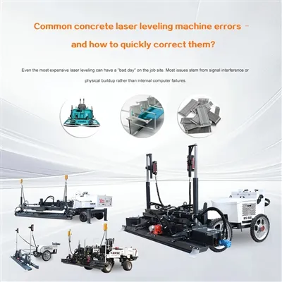
Even the most expensive laser leveling can have a "bad day" on the job site. Most issues stem from signal interference or physical buildup rather than internal computer failures. Here is a breakdown of the most common errors and the "on-the-fly" fixes to keep your pour on schedule. The machine head starts bouncing or stops adjusting because the receivers cannot "see" the laser transmitter. The Cause: Often "Line of Sight" issues. A truck, a pile of rebar, or even heavy dust/steam has blocked the beam. The Quick Fix: * Check the Transmitter: Ensure the laser tripod hasn't been bumped by a worker. Clean the Eyes: Use a soft cloth to wipe the receivers on the machine head. Concrete splatter or heavy dust acts like a blindfold. Relocate: If working in high heat, "heat shimmer" can refract the laser. Move the transmitter closer to the machine to shorten the distance the beam has to travel. The concrete looks like corduroy or has small ridges rather than a glass-smooth finish. The Cause: Usually an issue with travel speed or vibrator frequency. If you move too fast, the head "skips." If the vibrator is too high, it creates resonance waves. The Quick Fix: Slow Down: Reduce your pull speed by 10-15%. Tune the Vibrator: Adjust the frequency until the "cream" rises steadily without the head visibly shaking the wet concrete 3 feet in front of it. Check the Grade: Ensure your "Cold Start" (the initial manual height setting) wasn't set too high, forcing the machine to fight against too much excess material. The machine says it's on grade, but your manual check shows you are off by 1/4 inch or more. The Cause: Bench-set error or Differential Settling. The laser transmitter may have settled into soft ground or "drifted" due to wind vibration. The Quick Fix: Re-Bench: Periodically check the laser against a known physical benchmark (like a fixed wall mark) every hour. Tripod Stability: Move the transmitter to a "dead" spot (like a cured slab) rather than on raw dirt or near a running generator that causes vibration. The leveling head is jittery and constantly moving up and down in small, rapid increments. The Cause: The hydraulic gain (sensitivity) is set too high for the slump of the concrete you are using. The Quick Fix: * Adjust Gain Settings: Lower the "Gain" or "Sensitivity" on the control panel. This tells the hydraulics to be less aggressive when making corrections. Check Fluid: Ensure hydraulic fluid is at the proper temperature; "cold" oil can cause sluggish or jerky movements. Error Symptom Primary Suspect Action Bouncing Head High Gain / High Speed Lower gain; Slow down travel Laser Signal Loss Obstruction / Dirty Lens Clear path; Wipe receivers Inaccurate Grade Transmitter Drift Re-bench to a fixed point Heavy Slump Down Gravity / Over-vibration Reduce vibrator Hz; Use lower slump Are you currently seeing a specific error code on your control panel, or are you just prepping your crew for an upcoming pour? Contact us NOW Note: The parameters provided in this document are for reference only and are not mandatory. Due to differences in technical characteristics between different brands and models of laser levelers, please consult the manufacturer for a suitable solution before actual operation. This reference document assumes no responsibility for any issues arising from failure to follow the manufacturer's instructions.