Technical Knowledge
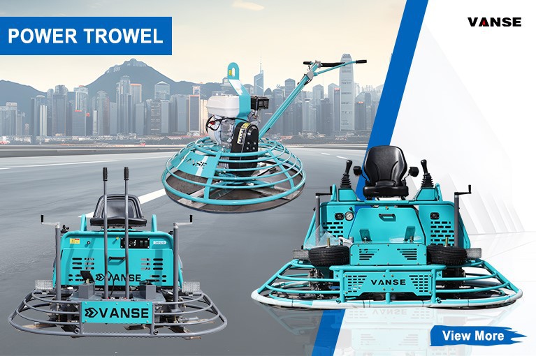
Techniques for Using a Power Trowel in Colored Concrete Flooring
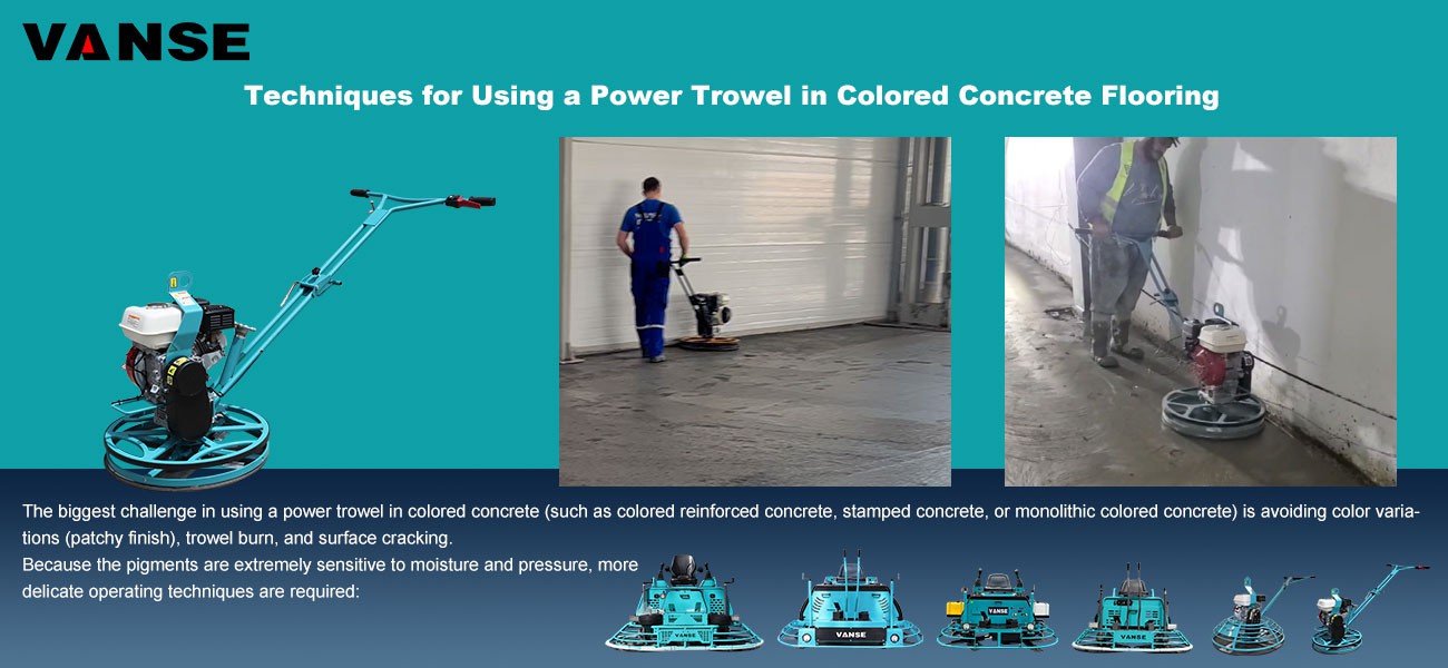
The biggest challenge in using a power trowel in colored concrete (such as colored reinforced concrete, stamped concrete, or monolithic colored concrete) is avoiding color variations (patchy finish), trowel burn, and surface cracking.
Because the pigments are extremely sensitive to moisture and pressure, more delicate operating techniques are required:
1. Core Operating Principles: From "Fast" to "Stable"
**Strictly Prohibited:** Never spray water onto the surface during the polishing process to make it easier to spread. Water will dilute the surface pigments, causing the color to lighten or resulting in efflorescence (whitening). If the surface dries too quickly, use a dedicated evaporative retarder.
**Spinning Speed Control:** On colored flooring, low to medium speed is recommended. High-speed rotation generates high temperatures, which can easily cause chemical reactions or physical "burning" of the surface metal oxide pigments, resulting in a blackening of the color.
**Plastic Blades (Critical):** For extremely high color consistency, it is recommended to replace the steel blades with **plastic blades** or blades with plastic protective covers. The black metal shavings produced by the friction between the steel blades and the concrete are the main cause of the "darkening" or blackening of colored flooring.
2. Application Techniques at Different Stages
A. Applying Color Hardener Stage (Raising the Grout)
First Coat Application: After applying the first coat of pigment, use a power trowel with a **float pan** attached to it at low speed to rub the pigment into the grout.
Avoid Over-Rubbing: The purpose of this step is to allow the pigment to absorb moisture from the grout and darken, not to completely polish it. Over-rubbing will lift the underlying gray concrete grout, contaminating the color.
B. Finishing Stage (Eliminating Color Difference)
Consistent Angle: When working in the same area, the blade angle must be consistent. A larger blade angle results in greater localized pressure, leading to a darker color.
Same Direction of Work: Maintain a consistent finishing direction as much as possible. Cutting lines in different directions will create visual color differences under light.
Control the Number of Finishing Coats: Compared to ordinary flooring, colored flooring should have fewer finishing coats. More coats result in a denser surface, increasing the risk of "scorching" and discoloration.
3. Special Process: Stamped Concrete
Power Trowel Finish: For stamped concrete, the power trowel operation ends before the release powder is applied.
Required Finish: The power trowel must achieve a smooth but not glossy surface. If the surface is too glossy or too matte, the release powder will not adhere properly, and the stamped texture will appear stiff and unnatural.
Common problems and solutions
| Fault Symptoms | Possible causes | Solutions |
| Burn marks | High temperature generated by high-speed friction of steel blades | Reducing the speed and replacing the blades with plastic ones. |
| Blotchy | Uneven water spraying or slurry distribution during troweling | Strictly prohibiting water spraying and increasing the initial disc leveling time. |
| Efflorescence | Excessive water-cement ratio or premature troweling | Strictly controlling the slump and waiting for the seepage to completely disappear. |
| Exposure | Trelmmer cutting too deep, removing the color layer | Lowering the blade angle to reduce machine weight. |
Note: The parameters provided in this document are for reference only and are not mandatory. Due to differences in technical characteristics between different brands and models of laser levelers, please consult the manufacturer for a suitable solution before actual operation. This reference document assumes no responsibility for any issues arising from failure to follow the manufacturer's instructions.
Thanks to All the Friends Who Support and Trust Shandong Vanse Machinery Technology Co., Ltd.
If you want to know more about Shandong Vanse Machinery Technology Co., Ltd. or have any questions, please feel free to contact us:
Our Factory
Shandong Vanse Machinery Technology Co., Ltd.

Share this article

About the Author: Shandong Vanse Machinery Technology Co., Ltd.
Shandong Vanse Machinery Technology Co., Ltd. is a high-tech manufacturer specializing in concrete construction machinery, including laser screeds and related equipment. The company integrates R&D, production, and global sales, with products exported to over 60 countries and widely used in infrastructure projects worldwide.
Previous Post
Next Post
Related Articles
You Might Also Like
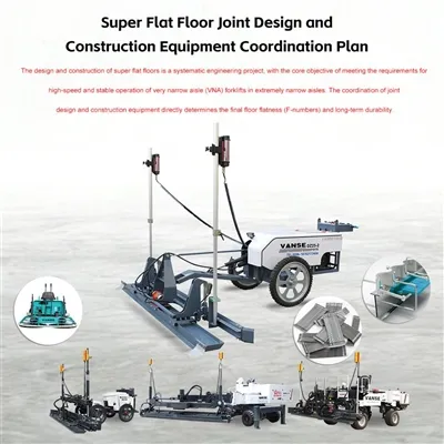
Super Flat Floor Joint Design and Construction Equipment Coordination Plan
The design and construction of super flat floors is a systematic engineering project, with the core objective of meeting the requirements for high-speed and stable operation of very narrow aisle (VNA) forklifts in extremely narrow aisles. The coordination of joint design and construction equipment directly determines the final floor flatness (F-numbers) and long-term durability. The following is a professional plan for super flat floor joint design and equipment coordination: Ultra-flat floor slabs typically follow the principle of "large slab spans and fewer joints" to reduce the impact of forklift wheels on the joints. Load Transfer Bar Design: Square load transfer bars or armored joints must be used. Armored joints consist of two cold-drawn flat steel bars, which effectively protect the concrete edges from being crushed by the hard wheels of forklifts. Placement: Avoid placing joints in the main forklift traffic areas as much as possible. In VNA (Very Narrow Aisle) areas, construction joints should be parallel to the aisles and ideally located under the racking rather than in the center of the aisle. Timing of cutting the joints: The joints should be cut after the concrete has initially set and reached a strength of 5-10 MPa, usually 6-12 hours after pouring. Spacing control: It is recommended to keep the spacing within 6m x 6m to prevent the formation of irregular, random cracks. The joints must be filled with **high-hardness polyurea** or semi-rigid epoxy resin to support the edges of the joint. The filler should slightly overflow during application, and after curing, the excess should be trimmed flush with a blade to ensure the joint is perfectly level with the floor surface. Achieving a super-flat floor relies not only on manual work but also on high-precision automated equipment. This is the core of super-flat floor construction. Equipment Selection: A telescopic-arm laser leveling machine with automatic leveling function is used. Coordination Key Points: The laser transmitter should be installed at a high location unaffected by vibrations. The leveling machine automatically adjusts the height of the leveling head at a frequency of 10 times per second to ensure the accuracy of the initial floor elevation. In some special tunnels requiring a flatness level of F min, the laser leveling process still needs to be supplemented with a side form guide rail system. Process: Precision channel steel or I-beams are used as guide rails, combined with manual verification using a Leveling bar, to ensure extremely high accuracy in both the transverse and longitudinal directions. Double-drive ride-on power trowel: Used for large-area concrete finishing and compaction. Recommended procedure: Must be used in conjunction with a **long-handled straightedge** for repeated leveling. After each pass with the power trowel, use a 3-4 meter long straightedge to level the surface in both longitudinal and transverse directions, eliminating any waves left by the trowel. Stages Core Equipment Key points for implementation Spreading and leveling Laser leveling machine + laser control system Ensure continuous material supply to prevent machine stoppages that could cause indentations. Initial leveling Long-handled aluminum-magnesium alloy Leveling (Check Rod) Before the concrete begins to set, manually smooth out any minor unevenness left by the leveling machine through repeated scraping. Grouting and finishing Ride-on power trowel + floating disc Strictly control the finishing time, adjusting the blade angle according to the concrete's hardening degree. Joint treatment Automatic self-propelled concrete saw + polyurea joint filling machine The cutting depth is typically 1/3 to 1/4 of the slab thickness. After construction is complete, the floor must be inspected using a professional **floor flatness testing instrument (such as Dipstick or FloorPro)**. FF (Floor Flatness): Reflects the flatness of the floor (small-scale undulations). FL (Floor Levelness): Reflects the levelness of the floor (large-scale inclination). Key reminder: The success of a super-flat floor depends 50% on equipment precision and 50% on controlling the concrete mix design (slump variation needs to be controlled within ± 20 mm). Note: The parameters provided in this document are for reference only and are not mandatory. Due to differences in technical characteristics between different brands and models of laser levelers, please consult the manufacturer for a suitable solution before actual operation. This reference document assumes no responsibility for any issues arising from failure to follow the manufacturer's instructions.How to construct concrete laser leveling machine in complex environment
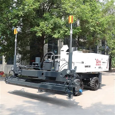
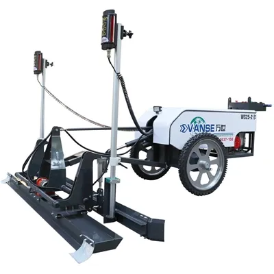
Concrete laser leveling operate in complex environments, requiring specialized plans tailored to specific environmental characteristics (such as confined spaces, areas with varying heights, inclement weather, and numerous obstacles), ensuring a balanced balance of efficiency, precision, and safety. The following details construction strategies and key technical points based on common complex environments: The core challenges of confined spaces are limited equipment maneuverability and the susceptibility of laser signals to obstruction. These limitations must be overcome through equipment selection and operational optimization. Select a compact machine: Prefer a small laser leveling (such as a walk-behind or mini-ride model) with a wheelbase ≤ 2.5m and a width ≤ 1.2m. Keep the minimum turning radius within 1.5m to allow for operation in narrow passages (widths ≥ 1.5m). Laser System Adaptation: Utilize multi-transmitter networking technology, placing 2-3 laser transmitters at different locations within the space (e.g., corners, near pillars) to prevent a single transmitter from being blocked by walls or pillars. Use anti-interference laser receivers (operating at 635nm red light or 532nm green light) to reduce signal interference from obstacles. Zoned and Miniaturized Operations: Divide a narrow space into multiple micro-blocks, such as 3m x 3m units, based on the equipment's operating radius (usually 2-3m). Work progresses zone by zone, avoiding frequent equipment maneuvers. Manually Assisted Spreading and Finishing: Due to space constraints, large-scale spreading equipment cannot be used. Manually spread the concrete in advance to a height 3-5cm above the design elevation (to reduce the burden on the equipment). Corners that cannot be reached by the equipment (e.g., walls and pillar bases) are manually leveled using aluminum alloy scrapers and vibrators to ensure a smooth transition with the machine work area. Real-time Signal Monitoring: Assign a dedicated person to monitor the laser receiver indicator light (green indicates normal operation, red indicates signal loss). Immediately stop the machine and adjust the transmitter position if a signal interruption is detected to avoid elevation errors caused by signal deviation. Precise control of elevation gradients is required in areas with complex level differences to avoid step-like errors. The key lies in the flexible adaptability and reference setting of the laser system. Slope Construction: Slope Sensor Interaction: Install a slope sensor (accuracy ±0.1%) on the leveling machine. Interact with the laser system to preset the laser plane inclination angle based on the designed slope (e.g., 2% or 5%). During operation, the machine automatically adjusts the scraper blade height according to the slope, ensuring that the elevation difference per meter meets the designed value (e.g., a 2% slope means a 2cm elevation difference per meter). Step/Platform Construction: Layered Reference Stakes: Set layered reference stakes (spacing ≤3m) at the intersection of height differences. Use a total station to calibrate the top elevation of the stakes. Mount the laser transmitter on the stakes to create a "stepped laser plane." Complete the lower elevation area first, then adjust the laser system parameters to accommodate the higher elevation area. Overlap the work at the intersection by 5-10cm. Preventing Segregation on Slopes: Control the concrete slump to 80-100mm (slightly lower than when working on flat ground) to prevent aggregate sinking due to the slope. Lay the concrete from the bottom of the slope toward the top, with each layer ≤20cm thick to prevent concrete from sliding down. Edge Height Adjustment: Set temporary barriers (height equal to the designed height difference) at the edge of the height difference (e.g., where the platform meets the ramp). After the equipment is in place, manually remove the barriers and trim the edges to ensure a height difference error of ≤3mm. Obstacles (e.g., rebar, pipelines, embedded components, walls) can hinder equipment movement and laser signals, requiring path planning and protective measures. Locate obstacles using 3D modeling: Utilize BIM technology or on-site surveying to mark the location, height, and spacing of obstacles (e.g., pipeline depth, rebar mesh elevation). Generate a feasible equipment route map, avoiding areas with dense obstacles (manual handling is preferred for areas with spacing ≤1m). "Obstacle Avoidance + Compensation" Combined Process: The equipment operates by circumventing obstacles 10-15cm from the edge. Pre-defined obstruction areas are manually compensated using a small vibrator (≤1m in length). After compensation, a 2m ruler is used to level the area with the machine work area to ensure a smooth connection. Signal Blind Spot Solutions: For areas blocked by walls or large structures, use wired references (e.g., installing aluminum alloy guide beams next to the obstacles, attaching the laser receiver to the guide beams, and using the guide beams to transmit the elevation reference). Alternatively, use a handheld laser leveler for real-time calibration of manually adjusted areas. Equipment Collision Protection: Install rubber anti-collision strips on the front of the equipment and wear-resistant alloy plates on the bottom of the scraper to prevent scratching rebar. During operation, a supervisor should be assigned to provide real-time distance between the equipment and obstacles, ensuring a safe distance of ≥5cm. Weather factors can affect concrete performance and equipment stability, requiring targeted adjustments to construction parameters and schedules. Concrete Temperature and Initial Setting Control: Use cooling aggregates (such as ice water mixing) to keep the concrete temperature at ≤ 30°C upon entering the mold. Add a retarding water reducer to extend the initial setting time (from 2-3 hours to 4-5 hours) to prevent initial setting before the equipment is fully operational. Protecting the Laser System from Sun Exposure: Install a sunshade for the laser transmitter to prevent direct sunlight from overheating and freezing the device. Regularly water the receiver to cool it down (keep the surface clean to prevent high temperatures from affecting signal reception sensitivity). Staggered Operation: Choose construction hours between 6:00 AM and 4:00 PM to avoid the midday heat, and shorten the interval between work steps (complete finishing within 30 minutes after leveling). Concrete Insulation and Freeze Protection: Use hot water mixing or add antifreeze to ensure the concrete temperature at ≥ 10°C upon entering the mold. Immediately cover the unused area with a blanket after paving to prevent low temperatures from reducing fluidity. Equipment Preheating and Lubrication: Preheat the engine for 10-15 minutes before starting. Run the hydraulic system at no load for 3-5 minutes until the oil temperature reaches ≥15°C to prevent component wear caused by low temperatures. Install the laser transmitter away from drafts and, if necessary, wrap it in an insulation cover to prevent frost. In high winds (wind speed ≥ Level 5): The laser transmitter must be mounted on a weighted base (weighing ≥50kg) or a windproof transmitter (wind resistance rating ≥ Level 8) must be used. During operation, reduce the laser reception range (adjust the receiver sensitivity to "high") to minimize wind-induced signal fluctuations. In Rain and Snow: In light rain, a temporary awning can be constructed (e.g., covering the work area with tarpaulin). Waterproofing can be added to the concrete. In moderate rain or snow, work should be suspended immediately. Cover the paved concrete with tarpaulin and drain the water. Before resuming work, check the moisture content of the base layer (≤10%). Unstable terrain can cause base settlement or equipment tilt, requiring enhanced base treatment and equipment support. Soft Base Treatment: Use a replacement method (replace with 30-50cm of graded sand and gravel) or reinforce with cement-soil mixing piles to ensure a base bearing capacity ≥150kPa to prevent equipment sinking during operation (settlement ≤2mm/h). Leveling Mountainous Terrain: First, use a bulldozer to roughly level the terrain (slope ≤10%). Then, lay a 10-15cm thick crushed stone cushion and compact it. This serves as the base for the laser leveling machine, reducing the need for frequent adjustments to the equipment due to uneven terrain. Track/Tire Grounding Treatment: Lay steel plates (thickness ≥ 10mm) or roadbed boxes on soft subgrade to increase the equipment's ground contact area (ground pressure ≤ 50kPa) and prevent the equipment from sinking. Tracked equipment can be tightened to improve its climbing ability (maximum climbing angle ≤ 15°). Real-Time Tilt Monitoring: The equipment is equipped with a horizontal tilt sensor that automatically alarms when the tilt angle exceeds 3°, prompting the operator to immediately adjust the equipment's position to avoid leveling errors caused by machine tilt. Emergency Plan Preparation: Develop contingency plans for equipment failure, signal interruption, and abnormal concrete supply, including backup laser transmitters, small generators (for power outages), and manual leveling tool kits (vibrator, scraper, trowel), etc. Real-Time Quality Inspection: After completing every 50 square meters, use a laser leveler (accuracy ±0.5mm) to check levelness. Areas with errors exceeding 5mm require immediate re-leveling to avoid further losses from rework. Specialized team training: Operators undergo complex environment simulation training, focusing on skills such as obstacle avoidance, signal calibration, and emergency shutdown, ensuring that each operator masters at least two emergency response methods. Through these strategies, the concrete laser leveling machine can achieve the goal of "maintaining accuracy and minimizing efficiency loss" in complex environments. The flatness pass rate remains above 90%, and operating efficiency only decreases by 10%-20% compared to conventional environments (400-500 square meters/day in conventional environments, 300-400 square meters/day in complex environments). The core principles are: proactively adapting to the environment, flexibly adjusting parameters, strengthening human-machine collaboration, and strictly controlling quality milestones. ARMOUR JOINT CONCRETE LASER LEVELING MACHINE POWER TROWEL TOPPING SPREADERWhat special attention should be paid to the maintenance and care of concrete laser leveling machines under different climatic conditions?
– Under high temperature environment, the engine (if it is a fuel laser leveler) and hydraulic system are prone to overheating. For the engine, make sure that the coolant in the radiator is sufficient and clean. The coolant level should be checked regularly, generally every 8-10 hours of work, and the coolant should be replaced regularly according to the requirements of the equipment manual. It is usually recommended to replace it once a year. – Clean the dust and debris on the surface of the radiator, as these will affect the heat dissipation effect. You can use a compressed air can or a soft brush to gently clean it to avoid damaging the radiator fins. – For the hydraulic system, some laser levelers are equipped with a hydraulic oil cooler. Also ensure that its surface is clean and pay attention to the temperature of the hydraulic oil. If the hydraulic oil temperature is too high, it may cause the performance of the hydraulic system to decline or even damage. – Try to avoid using the equipment for a long time when the temperature is highest during the day (usually 12 noon-3 pm). Because during the high temperature period, the operating temperature of each component of the equipment is already high, and long-term continuous operation will further aggravate heat accumulation and increase the risk of equipment failure. – The working time can be adjusted to the early morning or evening, when the ambient temperature is relatively low, which is conducive to the normal operation of the equipment. If it is unavoidable to work during high temperature periods, the rest frequency of the equipment should be increased. After every 1-2 hours of work, the equipment should be allowed to rest for 15-20 minutes to allow the various parts of the equipment to fully dissipate heat. – High temperature will accelerate the evaporation and aging of lubricating oil (grease), so the lubrication of the equipment should be checked more frequently. For example, for the bearings, chains and other parts of the equipment, lubrication may be performed once every 50-100 hours of work. In a high temperature environment, it is necessary to check and add grease every 30-50 hours of work. – At the same time, check the seals of the equipment, such as the seals at the joints of the hydraulic pipes and the engine oil seals. High temperature may cause the seals to age and deform, resulting in leakage. If the seals show signs of damage, they should be replaced in time to avoid leakage of hydraulic oil or coolant, which will affect the normal operation of the equipment. – For fuel-type laser levelers, use fuel suitable for low temperature environments. In cold weather, diesel may wax, which will affect the start and normal operation of the engine. You can add anticoagulants or use low-grade winter diesel to solve this problem. – Battery performance will decrease at low temperatures, so make sure the battery is fully charged. When the equipment is not in use, the battery can be removed and placed in a warm room for charging and storage. In addition, before starting the equipment, the battery can be preheated, such as using a battery heater, which can improve the battery's starting ability. – The engine should be fully preheated before starting. According to the requirements of the equipment manual, use a preheating device to preheat the engine. The preheating time is generally determined by the ambient temperature. For example, in an environment of about minus 10℃, the preheating time may take 10-15 minutes. – For the hydraulic system and working parts, do not let the equipment work at full load immediately after starting. Let the equipment run at no load for 5-10 minutes to gradually heat up the hydraulic oil and various components. After reaching the normal working temperature, start construction. – If the equipment is not used for a long time, it should be stored indoors or in a place with insulation measures to avoid exposure to cold outdoor environments. If it can only be stored outdoors, the equipment should be properly covered to prevent damage to the equipment caused by snow and ice. – Antifreeze can be added to the water tank and hydraulic oil tank of the equipment to prevent the water tank and oil tank from freezing and cracking at low temperatures. The amount of antifreeze added should be in accordance with the requirements of the equipment manual. Generally, the concentration of antifreeze should be ensured to effectively prevent freezing at the expected minimum temperature. – Check the electrical system of the equipment to ensure that all electrical components (such as motors, controllers, sensors, etc.) have good waterproof seals. For wire connectors exposed to the outside, waterproof tape or sealant can be used to wrap them to prevent moisture from entering and causing short circuits. – The laser transmitter and receiver of the laser leveling machine should also be waterproof. In humid weather, if these precision components are damp, it may affect the transmission and reception of laser signals, thereby affecting the construction accuracy. You can use a special waterproof cover to protect it. When the equipment is not in use, store these parts in a dry place. – Humid air can easily cause equipment to rust, especially the metal parts of the equipment. Anti-rust oil or anti-rust paint can be applied to the surface of the equipment, and the parts that are prone to rust (such as chassis, scrapers, screws, etc.) should be protected. – Regularly check whether the equipment has signs of rust. For rusted parts, rust removal should be carried out in time. You can use sandpaper or rust remover to remove the rust, and then apply anti-rust oil or touch-up paint. – After working in humid weather, the equipment should be cleaned and dried in time. Use a clean rag to wipe off the moisture on the surface of the equipment. For parts inside the equipment that may be damp (such as the cab, electrical control cabinet, etc.), a hair dryer or dehumidifier can be used to dry them. – At the same time, the working parts of the equipment (such as scrapers, spiral distributors, etc.) should be cleaned to prevent concrete residues and moisture from mixing and solidifying on the parts, affecting the next use of the equipment.