Technical Knowledge
Selection Strategy for Riding-Type VS Hand-held Trowel Machines: Large Warehouse VS Small Workshop
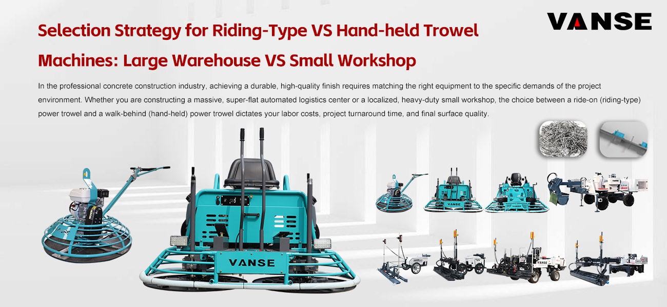
In the professional concrete construction industry, achieving a durable, high-quality finish requires matching the right equipment to the specific demands of the project environment. Whether you are constructing a massive, super-flat automated logistics center or a localized, heavy-duty small workshop, the choice between a ride-on (riding-type) power trowel and a walk-behind (hand-held) power trowel dictates your labor costs, project turnaround time, and final surface quality.
To maintain high E-E-A-T (Experience, Expertise, Authoritativeness, and Trustworthiness) standards in concrete flooring, contractors must deploy a strategic equipment selection process. Here is the ultimate guide to selecting the right concrete finishing machinery for your next project, featuring industry-leading insights and equipment solutions from Shandong Vanse Machinery Technology Co., Ltd. (www.vansemac.com).
Scenario 1: Large Warehouses and Logistics Centers
The Requirement: Massive daily pour volumes, strict international Floor Flatness (FF) and Floor Levelness (FL) tolerances, and high surface wear resistance.
The Solution: Ride-On Power Trowels
For expansive commercial and industrial spaces, the riding-type power trowel is the undisputed necessity. Utilizing walk-behind equipment in a massive warehouse is an operational bottleneck that dramatically inflates labor costs and risks the concrete curing before the finishing phase is complete.
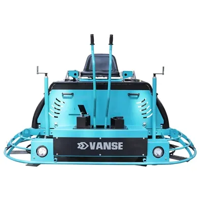
Superior Surface Compaction: Ride-on trowels, such as the heavy-duty models offered by Vanse Machinery, feature dual-rotor systems and weigh significantly more than hand-held units. This intense mechanical weight drives coarse aggregates down and brings the cement paste to the top, resulting in a highly densified, burnished finish that resists the heavy dynamic loads of forklifts and automated storage and retrieval systems (ASRS).
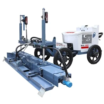
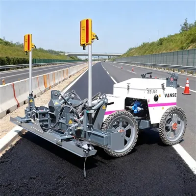
Protecting FF and FL Metrics: When pouring super-flat floors, contractors rely on advanced Concrete Laser Screeds (like the Vanse YZ30-4E or YZ40-4E telescopic boom models) to establish the perfect grade. A ride-on trowel operator sits on the machine, meaning no human footprints disrupt the freshly leveled surface. The wide, overlapping stance of the machine acts as a massive smoothing plane, locking in the laser-guided levelness.
Exponential Efficiency (OpEx Savings): A single operator on a high-speed ride-on trowel can cover thousands of square meters in a fraction of the time it takes a manual crew. This rapid turnaround is essential for preventing cold joints and keeping international construction projects ahead of schedule.
Scenario 2: Small Workshops and Confined Spaces
The Requirement: Maneuverability, cost-effectiveness, and precision around structural obstacles.
The Solution: Walk-Behind (Hand-Held) Power Trowels
Not every project has the square footage to justify the deployment of heavy riding equipment. For small workshops, residential garages, retail expansions, or tight mezzanine decks, the walk-behind power trowel is the strategic choice.
Unmatched Maneuverability: Walk-behind trowels excel in confined spaces. They can easily navigate around plumbing stub-outs, structural columns, and tight corners where a bulky ride-on machine simply cannot fit or safely maneuver.
Lower Capital Expenditure (CapEx): For smaller contracting firms or specialized repair teams, hand-held trowels require a much lower initial investment while still providing the mechanized blade rotation necessary for a smooth, hard trowel finish.
Ease of Transport: Walk-behind units are lightweight and can be easily loaded into standard service trucks or elevated to upper-deck projects without the need for heavy-duty telehandlers or cranes.
The Hybrid Strategy: Why Elite Contractors Require Both
For global contractors handling comprehensive commercial builds, the selection strategy is rarely "either/or." It is highly recommended to view concrete finishing as an integrated ecosystem.
As demonstrated by the comprehensive product lineup at Vanse Group, a flawless commercial floor requires a hybrid deployment:
The Primary Output: Deploy the Ride-On Power Trowel to handle the vast 90% of the open warehouse floor space, matching the rapid advancement of the laser Leveling.
The Perimeter Polish: Simultaneously deploy a team with Walk-Behind Power Trowels to follow the perimeter, expertly finishing the critical edge work along the formwork, walls, and structural pillars where the ride-on machine cannot safely reach.
Conclusion
Selecting the correct concrete power trowel is a direct calculation of project scale, labor economics, and required floor specifications. For vast, seamless industrial floors, ride-on trowels are critical for efficiency and super-flat compaction. For confined workshops and precise edge-work, walk-behind trowels remain indispensable.
By equipping your fleet with a balanced combination of reliable, high-performance machinery from an authoritative manufacturer like Shandong Vanse Machinery, you ensure your contracting business can competitively bid on-and flawlessly execute-any project, from the smallest workshop to the largest global logistics center.
Note: The parameters provided in this document are for reference only and are not mandatory. Due to differences in technical characteristics between different brands and models of laser levelers, please consult the manufacturer for a suitable solution before actual operation. This reference document assumes no responsibility for any issues arising from failure to follow the manufacturer's instructions.
Thanks to All the Friends Who Support and Trust Shandong Vanse Machinery Technology Co., Ltd.
If you want to know more about Shandong Vanse Machinery Technology Co., Ltd. or have any questions, please feel free to contact us:
Our Factory
Shandong Vanse Machinery Technology Co., Ltd.








Share this article

About the Author: Shandong Vanse Machinery Technology Co., Ltd.
Shandong Vanse Machinery Technology Co., Ltd. is a high-tech manufacturer specializing in concrete construction machinery, including laser screeds and related equipment. The company integrates R&D, production, and global sales, with products exported to over 60 countries and widely used in infrastructure projects worldwide.
Previous Post
Next Post
Related Articles
You Might Also Like
The development of concrete laser leveling machine is the need of the times!
The development of concrete laser leveling machine is the need of the times! The concrete laser leveling machine adopts the principle of laser leveling, which is more scientific and accurate than the traditional manual measurement method, and greatly reduces the error value caused by manual measurement. For some environments that require ultra-flat ground Said that this way of working is more acceptable and more in line with the needs of users. (1) The leveling principle of the laser leveling machine is realized under the automatic control of the computer by using precision laser technology, closed-loop control technology and highly precise hydraulic system. This is the most prominent difference between it and other floor construction processes. specialty. (2) The leveling principle of the precision laser leveling machine is to rely on the leveling head driven by hydraulic power, cooperate with the laser system and the computer control system to complete the leveling work while automatically leveling. The leveling head is equipped with an integrated scraper, vibrator and leveling plate, which integrates all leveling, leveling, vibration and compaction work, and completes it at one time. The computer control system automatically adjusts the elevation 10 times per second in real time, and the vibration frequency of the vibrator with a balanced design reaches 3000 times per minute. (3) The laser transmitter used to control the ground level is arranged independently, so that the level of the ground is not controlled by the template, and no cumulative error will occur. The original traditional labor-intensive operation methods no longer meet the needs of development. The integration of machinery and equipment and intelligence must have become the mainstream of the times. The current construction industry has already adopted laser leveling machines to replace the traditional ground paving mode. Rapid paving of large areas can ensure the quality of construction. The ground paved by this equipment is more flat and compact, so that the flatness of the ground is guaranteed. The laser leveling machine has a high leveling ground, which significantly improves the flatness of the ground. The ground constructed by the laser leveling machine and the traditional method are tested at 22 points (one point every 5mx4m), and the average flatness is 1.3mm and 4.1mm respectively. The leveling quality of the laser leveling machine can be improved by more than 3 times compared with the traditional method. Reduce the amount of side formwork dismantling: Based on the statistics of 20,000 square meters of concrete pavement, the traditional method needs to dismantle 5800m of side formwork, but with advanced equipment such as laser leveling machines, the dismantling of 2500m can reduce the support modulus by more than 74%. Fast construction speed: use laser leveling machine and other equipment to construct large slabs, which improves the work efficiency by 3 times compared with the traditional beam vibrator method, saves 30%, and can complete 3000 square meters per day on average, especially suitable for large-scale concrete surface construction. High degree of automation and low labor intensity: the use of laser leveling machine equipment can change the heavy manual labor into mechanical paving, vibrating, leveling, pulp extraction, and surface plastering, reducing the number of operators by 30% and reducing labor intensity. The application of equipment such as laser leveling machines can realize large-scale construction, effectively reduce a large number of construction joints, and the concrete slump can also be significantly reduced. The concrete strength is guaranteed, so that the ground integrity is good and cracks are not easy to appear. High economic benefit, the use of laser leveling machine can save 2-3 yuan per square meter compared with the traditional process, less seams, and lower maintenance costs in the later period, so that the economic benefit can be significantly improved.Cement Floor Cracks: Cause Analysis and Prevention
Cracks in cement floors (typically referring to cement concrete surfaces, such as indoor floors, outdoor plazas, and parking lots) not only affect appearance but can also reduce durability and even hinder functionality due to water seepage and debris accumulation. The following detailed analysis covers common crack symptoms, core causes, and targeted prevention and control measures to help accurately identify and effectively resolve the problem. The form, width, and distribution of cement floor cracks directly reflect their causes and can be categorized as follows: Crack Types Appearance Characteristics Common Locations Hazard Level Surface Cracks Cracks are short and thin (<0.1mm wide), forming an irregular network with no discernible depth, mostly concentrated in the surface layer (1-3mm deep). Large indoor floors and outdoor plazas Low (appearance only, no structural risk) Vertical/Horizontal Cracks Cracks are long (several to tens of meters long), straight, 0.1-0.5mm wide, and can penetrate the surface layer (5-10mm deep). Along the length/width of the floor, or along both sides of a partition joint Medium (easy to seep, accelerating surface degradation) Cracks at the Edges and Corners of Plates Cracks extend from the corners of the slab (such as the corners of a square floor) toward the center, forming an L-shaped or diagonal pattern, with a width of 0.2-0.8mm. At the joints of indoor and outdoor floor panels, near wall corners High (likely to cause edge peeling, affecting pedestrian safety) Through-Breaking Cracks Cracks extend through the entire cement surface layer (even penetrating the base layer), are >0.5mm wide, and are sometimes accompanied by slight ground subsidence or sanding. Highly loaded areas (such as parking lots and warehouses), and areas with uneven subgrades Extremely High (may cause floor damage and water accumulation, requiring urgent attention) The root cause of cement floor cracking is "internal stress in the surface layer exceeding its tensile strength." The sources of this stress are related to five key factors: material, base layer, construction, environment, and usage. The details are as follows: Improper material selection or proportioning directly leads to insufficient crack resistance in the surface layer: Incorrect cement selection: Using cement with a high heat of hydration (such as P.O. 42.5R rapid-hardening cement) to cast large surfaces releases a large amount of heat during hydration, raising the internal temperature of the surface layer. Contraction upon cooling creates "temperature stress," which can cause longitudinal and transverse cracks. Using expired cement (which has reduced strength) can also lead to insufficient tensile strength in the surface layer, making it more susceptible to cracking. Poor aggregate grading: If the fine aggregate (sand) is too fine (fineness modulus <2.3) or the mud content is too high (>3%), the cement requirement will increase (more cement paste is needed to coat the aggregate), leading to increased shrinkage of the surface layer. If the coarse aggregate (stone) is too small (<5mm) or missing, it will not form a "skeletal support," resulting in unrestrained shrinkage of the surface layer and prone to network cracking. If the water-cement ratio is too high: In pursuit of fluidity during construction, water usage is often blindly increased (water-cement ratio > 0.55). After the surface layer hardens, excess water evaporates, creating internal voids and reducing density. This significantly increases shrinkage (approximately 20% increase in shrinkage for every 0.1 increase in water-cement ratio), which can easily lead to surface cracking and edge cracking. Improper admixtures/admixtures: Failure to add or incorrect addition of admixtures (e.g., failure to add a retarder in summer, resulting in rapid initial setting of the surface layer and inability to grout after surface water evaporates; failure to add an antifreeze in winter, resulting in internal structural damage after freezing); and failure to add admixtures such as fly ash and mineral powder (key to reducing hydration heat and shrinkage) result in poor crack resistance in the surface layer. Cement floor surfaces rely on the stable support of a base layer (such as a lime soil base, crushed stone base, or concrete base). Base layer problems can directly affect the surface layer: Uneven base layer settlement: If the base layer is not compacted layer by layer during construction (e.g., a lime soil base with a compaction level less than 95%), or if there is a weak soil layer beneath the base layer (e.g., uncompacted backfill), the surface layer can experience partial subsidence during use, subjecting it to tensile stress and causing through-hole cracks or cracks at the edges and corners of the slabs. Uneven/contaminated base layer surface: The base layer surface has a height difference greater than 5mm (not leveled). The surface layer has uneven thickness after pouring, with thinner areas shrinking faster than thicker areas, creating "temperature differential stress." Oil and loose dust on the base layer surface have not been cleaned, resulting in insufficient adhesion between the surface layer and the base layer. After hardening, the two separate, and the surface layer shrinks independently, causing cracks. No isolation layer is provided for the base layer: When the base layer is concrete or a rigid material, without an insulating layer such as polyethylene film, the surface layer adheres too tightly to the base layer. During shrinkage, it is constrained by the base layer and cannot deform freely, causing cracks in areas of stress concentration (such as corners and joints). Construction operation is critical to crack control. Common mistakes include: Improper pouring and vibration: Failure to follow the "staged pouring, gradual progress" principle during pouring (e.g., large areas of ground are not divided into blocks, with individual blocks >20 m2), resulting in no channels for the surface layer to shrink as a whole; insufficient vibration during vibration (low density in some areas of the surface layer, insufficient tensile strength) or over-vibration (aggregate sinks, cement slurry floats, forming a "floating slurry layer" on the surface. After hardening, the floating slurry shrinks and cracks, known as crazing). Incorrect timing of surface calendering: Calendering too early (the surface layer has not yet set and the cement slurry has not yet developed strength) can easily cause sanding on the surface; calendering too late (the surface layer has already set and a crust has formed on the surface) can damage the surface structure, forming microcracks that later expand into cracks. Inadequate or improper sizing of the slurry: Large areas of flooring (single floor area >15 m2) are not provided with standardized expansion joints (spacing: ≤6 m vertically, ≤8 m horizontally). This lack of "stress relief" during surface shrinkage can lead to vertical/transverse cracks along weak areas (such as the center). Insufficient expansion joint depth (<1/3 of the surface layer thickness) or inadequate filler (such as asphalt mortar) can cause cracks to extend along both sides of the expansion joints. Untimely/inadequate curing: Failure to cover and cure the surface layer within 12 hours of pouring (e.g., exposure to direct sunlight in summer or wind in winter) allows surface moisture to evaporate rapidly, preventing internal moisture from being replenished. This results in "shrinkage stress" and causes surface cracking. Insufficient curing time (<7 days) prevents the surface layer from reaching its designed strength (typically ≥70% strength), leading to premature loading (e.g., pedestrians or vehicles), which can easily lead to corner cracks or through-hole cracks. Ambient temperature and humidity fluctuations can exacerbate stress in the surface layer and induce cracks: Severe Temperature Fluctuations: In summer, during daytime pouring (ambient temperature 35°C), the temperature drops sharply at night (15°C). The surface layer cools and contracts rapidly, while the interior cools and contracts slowly. This internal constraint creates "temperature stress" on the surface, leading to longitudinal, straight cracks. In winter, if the surface layer freezes before reaching its frost resistance (≥70% of design strength), the internal moisture freezes and expands, and upon thawing, the volume contracts, forming "freeze-thaw cracks" (mostly cracks at the edges and corners of the slabs, accompanied by surface spalling). Chronic and unstable humidity: In humid environments (such as bathrooms and underground garages), the surface layer absorbs moisture over time, softening the cement paste and reducing its tensile strength. In dry environments (such as heated rooms and warehouses in northern China), moisture from the surface layer continuously evaporates, accumulating shrinkage stress. The alternating effects of these two factors can easily lead to surface cracking or through-hole cracks. Improper load or maintenance during use can accelerate the development of cracks: Premature loading or overloading: Heavy objects (such as furniture and building materials) are piled on the surface before it reaches its design strength (28 days), or vehicles are driven on it (for example, a parking lot is opened to traffic without proper maintenance). This causes the surface to be subjected to loads exceeding its tensile strength, leading to through-cracks or cracks along the edges of the slabs. Lack of routine maintenance: Failure to promptly seal small cracks in the surface allows rainwater and oil to seep in, eroding the surface's internal structure. Furthermore, in winter, the water that seeps in freezes and expands, causing cracks to widen. Prolonged exposure to heavy loads (such as frequent forklift traffic in a warehouse) can lead to localized stress concentrations, causing longitudinal cracks. The core of prevention and control lies in "source control (materials + base layer), process control (construction), and post-maintenance (environment + use)." It is divided into two parts: "preventive measures" and "crack repair measures": Precise Material Selection: Prioritize cement with low hydration heat (such as P.O. 42.5 ordinary cement or slag Portland cement); use well-graded medium sand (fineness modulus 2.3-3.0, mud content ≤3%) and 5-10mm continuously graded crushed stone (mud content ≤1%) as aggregates; add Grade I fly ash (15%-20%) or mineral powder (20%-25%) to reduce hydration heat and shrinkage. Strictly control the water-cement ratio: The water-cement ratio should be ≤ 0.5 (for standard floors) and ≤ 0.45 (for impermeable floors). If necessary, add a retarding water reducer (at a dosage of 0.5%-1%) to maintain fluidity while reducing water consumption and minimizing shrinkage risk. Ensure the base layer is compacted and leveled: The base layer (lime soil/gravel) should be constructed in layers, with each layer ≤30cm thick and a compaction level ≥95% (tested using the knife ring method). The base layer surface should be leveled with cement mortar, with a height difference ≤3mm and cleaned (free of oil stains and loose dust). Apply a primer if necessary (to enhance adhesion between the surface layer and the base layer). Installing Isolation Layers and Expansion Joints: For rigid base layers (such as concrete), lay a 0.1mm thick polyethylene film isolation layer. For base layers >10m long, install expansion joints every 6-8m along the length (20mm wide and filled with asphalt hemp) to prevent base layer shrinkage from transferring to the surface layer. Scientific pouring and vibrating: For large floor areas, pour in blocks, with each block ≤15 m2 (rectangular blocks, aspect ratio ≤1.5). Leave 20 mm wide joints between blocks (the joint depth should be 1/3-1/2 the surface layer thickness). Vibrate with a flat vibrator (at a speed of 1-1.5 m/min) until the surface is free of bubbles and slurry. Avoid missed or over-vibration. Choose the right timing for calendering: Calender in three steps: ① Before initial setting (after the surface layer has absorbed water), smooth it with a wooden trowel; ② After initial setting (no visible finger marks remain), perform initial compaction with an iron trowel; ③ Before final setting (when the surface is nearly hardened), perform final compaction with an iron trowel to ensure a smooth surface without any marks. Strengthened maintenance management: Cover the surface with geotextile or plastic film (add a shade net in summer and a thermal blanket in winter) within 12 hours after pouring to keep the surface moist. Curing time for ordinary surfaces is ≥7 days, and for impermeable/load-bearing surfaces is ≥14 days. Pedestrians and vehicles are prohibited from entering during the curing period. Temperature Control: In summer, avoid pouring at noon (select morning and evening temperatures between 25-30°C). Cover the surface to maintain moisture. In winter, preheat the aggregate (≥5°C) before pouring, ensure the surface is at least 10°C before pouring, and maintain an ambient temperature of ≥5°C during curing (use heating if necessary). Usage and Management: The surface should be cured for 28 days before use. Premature stacking of heavy objects is prohibited. In areas such as parking lots and warehouses, limit vehicle/cargo weight to the designed load capacity to avoid local overloading. Regularly inspect the floor surface and seal any minor cracks with epoxy resin glue. If cracks have already appeared, first clean them (remove debris and dust, and flush with a high-pressure water gun), then repair them as follows: Crack Types: Repair methods Material Selection Key Points: Surface cracks Surface sealing method Epoxy sealer, cement-based penetrating crystallization coating (CCCW) Use a brush to evenly apply the glue/paint to the crack surface and a 5cm area on either side. Repeat 2-3 times. Cure for 24 hours. Vertical/horizontal cracks (width < 0.5mm) Low-pressure grouting method Cement slurry (water-cement ratio 0.45), epoxy slurry Drill an 8mm diameter hole (5mm deep) every 20cm along the crack. Insert a grouting tube and inject grout using a low-pressure pump (0.2-0.3MPa) until the grout overflows. Cure for 7 days. Cracks along edges and corners (width 0.2-0.8mm) Painting mortar filling method Polymer cement mortar (cement: sand: latex = 1:2:0.15) Chisel away the loose surface layer on both sides of the crack (5-10cm wide, 3-5mm deep). Clean and apply a primer. Fill with mortar and compact. Cure for 7 days. Through cracks (width > 0.5mm) Grouting + reinforcement method High-strength epoxy slurry, carbon fiber cloth First, fill the crack with high-pressure grouting (1.0-1.5MPa). Then, apply carbon fiber cloth (15cm wide, along the crack). Apply a topcoat. Cure for 14 days. The key to preventing and controlling cracks in cement floors is "prevention is better than cure": By optimizing the material mix (controlling the water-cement ratio and adding admixtures), stabilizing the base layer (compacting, leveling, and insulating layers), and standardizing construction (block-by-block pouring, timely maintenance, and appropriate gridding), stress can be reduced at the source. If cracks have already occurred, appropriate repair methods should be selected based on the crack morphology (width, depth, and location) to prevent further crack expansion. Paying attention to load control and regular maintenance during daily use can significantly extend the service life of cement floors. Note: The parameters provided in this document are for reference only and are not mandatory. Due to differences in technical characteristics between different brands and models of laser levelers, please consult the manufacturer for a suitable solution before actual operation. This reference document assumes no responsibility for any issues arising from failure to follow the manufacturer's instructions.What are the advantages and disadvantages of electric concrete trowels and internal combustion concrete trowels?
– Environmental protection and energy saving: Electric trowels are powered by electricity and do not produce exhaust gas emissions. They are more environmentally friendly and have relatively low operating costs. Long-term use can save energy costs. – Less noise: Compared with internal combustion trowels, electric trowels produce relatively low noise when working, which helps reduce noise pollution at the construction site, improve the working environment, and reduce noise interference to surrounding residents and operators. – Easy to operate: The structure of the electric trowel is relatively simple and easy to operate. Usually, you only need to connect the power supply and press the switch to start. There is no need to perform complicated operations such as refueling and starting like the internal combustion trowel. In addition, the speed of the electric trowel is relatively stable, and it is easy to control the leveling and polishing effect. – Low maintenance cost: Since the electric trowel does not have complex mechanical parts such as internal combustion engines, it does not need to regularly replace engine oil, air filters, etc. Its maintenance work mainly focuses on the inspection and cleaning of parts such as motors, wires and switches. The maintenance cost is relatively low and maintenance is also relatively convenient. – Dependence on power supply: The electric trowel needs to be connected to an external power supply to work, which limits its working range and flexibility. In some construction sites without power sockets, it is necessary to equip a longer power cord or use a generator to provide electricity, which is not convenient to use, and the existence of the power cord may affect the convenience and safety of operation. – Limited power output: Generally speaking, the power output of the electric trowel is weaker than that of the internal combustion trowel. For large-area, high-intensity concrete troweling operations, it may take longer to complete the task, and the work efficiency is relatively low. – Not suitable for harsh environments: When using an electric trowel in a humid or dusty environment, special attention should be paid to the waterproofing and dustproofing of the motor and wires to avoid safety accidents such as leakage or short circuit, which will affect the normal use and life of the equipment. – Powerful: The internal combustion trowel uses gasoline or diesel engines as the power source, has high power and torque output, can easily cope with various complex concrete troweling conditions, and is especially suitable for large-area, high-strength concrete surface troweling operations. It has high work efficiency and can complete a large amount of work in a short time. – Not limited by power supply: The internal combustion trowel does not need to rely on external power supply, can be operated anytime and anywhere, has high flexibility and mobility, and is particularly suitable for use in some remote areas or construction sites without power supply. – Environmental pollution: The internal combustion engine will produce exhaust emissions during operation, which contain pollutants such as carbon monoxide, hydrocarbons, and nitrogen oxides, which will cause certain pollution to the environment and are not conducive to environmental protection. – High noise: The internal combustion trowel generates a lot of noise during operation, which will cause certain damage to the surrounding environment and the hearing of the operator, and may also affect the life and rest of residents near the construction site. – High maintenance cost: The engine and other mechanical parts of the internal combustion trowel are relatively complex and require regular maintenance and upkeep, such as changing the engine oil, air filter, spark plug, etc. The maintenance cost is relatively high, and the engine maintenance also requires professional technology and tools. Once a failure occurs, the maintenance difficulty and cost are high. – Fuel consumption: The internal combustion trowel needs to consume fuel to provide power. After long-term use, the fuel cost is high. In some areas, the supply of fuel may not be as convenient as electricity, and fuel needs to be reserved in advance, which increases the complexity and cost of use.