Technical Knowledge
Selection and Installation Key Points of Formwork Systems in Super Flat Floor Construction
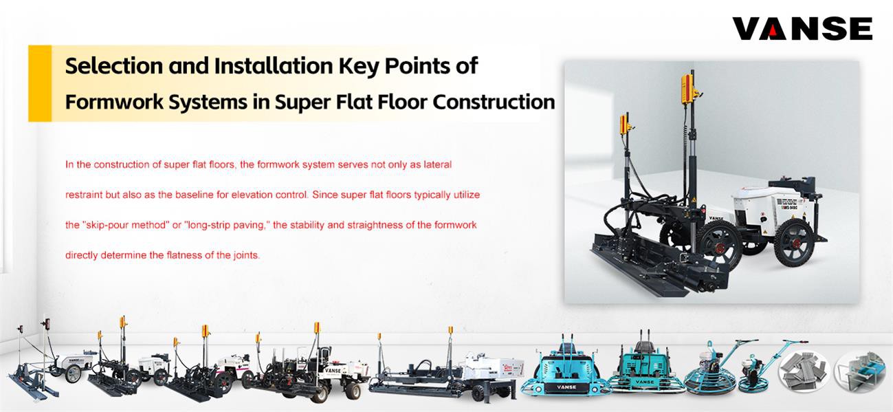
In the construction of super flat floors, the formwork system serves not only as lateral restraint but also as the baseline for elevation control. Since super flat floors typically utilize the "skip-pour method" or "long-strip paving," the stability and straightness of the formwork directly determine the flatness of the joints.
The following are key points regarding the selection and installation of formwork systems for super flat floors:
I. Selection of Formwork System
Traditional wooden formwork has been phased out in super-flat floor construction due to its susceptibility to deformation and low strength. The current mainstream solutions are as follows:
1. Armoured Joint System – Preferred Solution
Composition: Consists of two cold-drawn steel corner guards, load transfer bars, breakable bolts, and a lower steel plate.
Advantages: No need to remove after construction; it remains in the floor as a permanent joint; effectively protects the concrete edges from impact damage by forklift wheels (prevents chipping).
Applicable to: Longitudinal construction joints in very narrow aisle (VNA) areas.
2. High-precision channel steel or specially made steel molds
Requirements: Must possess sufficient rigidity, and the top surface must be machined and leveled.
Advantages: When used with a laser leveling machine, it can serve as a physical reference for the leveling head.
II. Key Installation Points
The accuracy of template installation directly affects the FL (Levelness) value, and the following steps must be followed:
1. Measurement and Positioning
Precise elevation control: Use a high-precision leveling instrument (accuracy requirement within ± 0.5 mm ) for surveying.
Denser measurement points: Set a fixed control point every 2 ~ 3 m along the template support trajectory to ensure straightness over long distances.
2. Secure Support
Reinforcement design: The template must be firmly anchored to the base layer using steel reinforcement bars. In ultra-flat floor construction, the power trowel is heavy and vibrates strongly; even a 1 mm settlement of the template will result in unacceptable flatness in that area.
Gap sealing: The gap between the bottom of the template and the base layer should be sealed with mortar to prevent leakage and the resulting "root rot" phenomenon, otherwise it will lead to honeycomb and pockmarked surfaces at the edges.
3. Precise Placement of Dowel Bars
Perpendicularity requirement: Dowel bars must be strictly parallel to the floor surface and perpendicular to the template surface.
Displacement control: The use of dowel bar sleeves or supports is recommended. If the dowel bars tilt during pouring, it will cause irregular cracks in the concrete during shrinkage, rather than cracking at the predetermined joints.
III. Construction Details and Equipment Coordination
| Key processes | Technical Requirements | Equipment coordination |
| Top surface cleaning | No old concrete or foreign objects shall remain on the top surface of the formwork. | Manual inspection with a trowel is performed before pouring. |
| Joint connection | The connection between two formwork sections must have a "zero height difference" transition. | A tongue-and-groove joint structure or reinforcing steel plates on the back are used. |
| Demolding time | The side formwork (non-armored joint) must be removed after the concrete strength reaches 2 to 3 MPa. | Avoid using a sledgehammer to pry, to prevent damage to the edges of the newly poured concrete. |
IV. Installation Diagram and Instructions for Armored Joints
When installing armored joints, it is important to pay attention to their three-dimensional adjustability. Adjustable height bolt supports are typically used, allowing for fine-tuning before concrete pouring to ensure the top surface of the angle steel is precisely at the design elevation.V. Common Misconceptions and Corrections
Misconception 1: Relying on laser Leveling without paying attention to formwork.
Truth: When working near the edges of the formwork, laser Leveling are limited by the width of the Leveling blade and edge interference, often requiring the formwork as a physical reference. If the formwork is uneven, the flatness of the edges will inevitably be compromised.
Misconception 2: Dowel bars are inserted directly through wooden formwork.
Truth: This makes it very easy to dislodge the dowel bars during formwork removal, damaging the bond between the dowel bars and the initial setting concrete. It is recommended to use armored joints or steel formwork with professional sleeves.
Note: The parameters provided in this document are for reference only and are not mandatory. Due to differences in technical characteristics between different brands and models of laser levelers, please consult the manufacturer for a suitable solution before actual operation. This reference document assumes no responsibility for any issues arising from failure to follow the manufacturer's instructions.
Thanks to All the Friends Who Support and Trust Shandong Vanse Machinery Technology Co., Ltd.
If you want to know more about Shandong Vanse Machinery Technology Co., Ltd. or have any questions, please feel free to contact us:
Our Factory
Shandong Vanse Machinery Technology Co., Ltd.








Share this article

About the Author: Shandong Vanse Machinery Technology Co., Ltd.
Shandong Vanse Machinery Technology Co., Ltd. is a high-tech manufacturer specializing in concrete construction machinery, including laser screeds and related equipment. The company integrates R&D, production, and global sales, with products exported to over 60 countries and widely used in infrastructure projects worldwide.
Previous Post
Next Post
Related Articles
You Might Also Like
What special attention should be paid to the maintenance and care of concrete laser leveling machines under different climatic conditions?
– Under high temperature environment, the engine (if it is a fuel laser leveler) and hydraulic system are prone to overheating. For the engine, make sure that the coolant in the radiator is sufficient and clean. The coolant level should be checked regularly, generally every 8-10 hours of work, and the coolant should be replaced regularly according to the requirements of the equipment manual. It is usually recommended to replace it once a year. – Clean the dust and debris on the surface of the radiator, as these will affect the heat dissipation effect. You can use a compressed air can or a soft brush to gently clean it to avoid damaging the radiator fins. – For the hydraulic system, some laser levelers are equipped with a hydraulic oil cooler. Also ensure that its surface is clean and pay attention to the temperature of the hydraulic oil. If the hydraulic oil temperature is too high, it may cause the performance of the hydraulic system to decline or even damage. – Try to avoid using the equipment for a long time when the temperature is highest during the day (usually 12 noon-3 pm). Because during the high temperature period, the operating temperature of each component of the equipment is already high, and long-term continuous operation will further aggravate heat accumulation and increase the risk of equipment failure. – The working time can be adjusted to the early morning or evening, when the ambient temperature is relatively low, which is conducive to the normal operation of the equipment. If it is unavoidable to work during high temperature periods, the rest frequency of the equipment should be increased. After every 1-2 hours of work, the equipment should be allowed to rest for 15-20 minutes to allow the various parts of the equipment to fully dissipate heat. – High temperature will accelerate the evaporation and aging of lubricating oil (grease), so the lubrication of the equipment should be checked more frequently. For example, for the bearings, chains and other parts of the equipment, lubrication may be performed once every 50-100 hours of work. In a high temperature environment, it is necessary to check and add grease every 30-50 hours of work. – At the same time, check the seals of the equipment, such as the seals at the joints of the hydraulic pipes and the engine oil seals. High temperature may cause the seals to age and deform, resulting in leakage. If the seals show signs of damage, they should be replaced in time to avoid leakage of hydraulic oil or coolant, which will affect the normal operation of the equipment. – For fuel-type laser levelers, use fuel suitable for low temperature environments. In cold weather, diesel may wax, which will affect the start and normal operation of the engine. You can add anticoagulants or use low-grade winter diesel to solve this problem. – Battery performance will decrease at low temperatures, so make sure the battery is fully charged. When the equipment is not in use, the battery can be removed and placed in a warm room for charging and storage. In addition, before starting the equipment, the battery can be preheated, such as using a battery heater, which can improve the battery's starting ability. – The engine should be fully preheated before starting. According to the requirements of the equipment manual, use a preheating device to preheat the engine. The preheating time is generally determined by the ambient temperature. For example, in an environment of about minus 10℃, the preheating time may take 10-15 minutes. – For the hydraulic system and working parts, do not let the equipment work at full load immediately after starting. Let the equipment run at no load for 5-10 minutes to gradually heat up the hydraulic oil and various components. After reaching the normal working temperature, start construction. – If the equipment is not used for a long time, it should be stored indoors or in a place with insulation measures to avoid exposure to cold outdoor environments. If it can only be stored outdoors, the equipment should be properly covered to prevent damage to the equipment caused by snow and ice. – Antifreeze can be added to the water tank and hydraulic oil tank of the equipment to prevent the water tank and oil tank from freezing and cracking at low temperatures. The amount of antifreeze added should be in accordance with the requirements of the equipment manual. Generally, the concentration of antifreeze should be ensured to effectively prevent freezing at the expected minimum temperature. – Check the electrical system of the equipment to ensure that all electrical components (such as motors, controllers, sensors, etc.) have good waterproof seals. For wire connectors exposed to the outside, waterproof tape or sealant can be used to wrap them to prevent moisture from entering and causing short circuits. – The laser transmitter and receiver of the laser leveling machine should also be waterproof. In humid weather, if these precision components are damp, it may affect the transmission and reception of laser signals, thereby affecting the construction accuracy. You can use a special waterproof cover to protect it. When the equipment is not in use, store these parts in a dry place. – Humid air can easily cause equipment to rust, especially the metal parts of the equipment. Anti-rust oil or anti-rust paint can be applied to the surface of the equipment, and the parts that are prone to rust (such as chassis, scrapers, screws, etc.) should be protected. – Regularly check whether the equipment has signs of rust. For rusted parts, rust removal should be carried out in time. You can use sandpaper or rust remover to remove the rust, and then apply anti-rust oil or touch-up paint. – After working in humid weather, the equipment should be cleaned and dried in time. Use a clean rag to wipe off the moisture on the surface of the equipment. For parts inside the equipment that may be damp (such as the cab, electrical control cabinet, etc.), a hair dryer or dehumidifier can be used to dry them. – At the same time, the working parts of the equipment (such as scrapers, spiral distributors, etc.) should be cleaned to prevent concrete residues and moisture from mixing and solidifying on the parts, affecting the next use of the equipment.With the advent of laser leveling machines, are you still using the old vibrating leveler to vibrate the beam?
With the advent of laser leveling machines, are you still using the old vibrating leveler to vibrate the beam? When it comes to construction, everyone knows that only with a short construction period and high quality can we save costs, improve efficiency and increase profits. If you want to save costs quickly during construction, construction tools are a very important choice. An efficient, convenient and fast tool will make construction work more effective with half the effort! On the contrary, choosing inappropriate tools will extend the construction period, increase costs, and reduce profits. Take the floor construction under construction as an example! The flatness of the floor is more difficult to grasp. Leveling is usually done manually. Even if you use an old-fashioned floor machine, the effect and cost are not particularly ideal. The emergence of a laser leveling machine has greatly solved many problems that arise during construction. During the construction process, it can solve the problems of hollowing, shelling, cracking, and uneven ground after general construction. It can make the final effect exceed Party A's floor quality requirements, reduce costs, and Improved work efficiency. Many industries require factories, as well as shopping malls, large warehouses and other construction sites that require large areas of ground, to have much higher standards. Attention has been greatly increased to the strength, flatness and level of the ground quality. It is difficult to meet the requirements using old-fashioned flooring methods, and labor costs will increase exponentially. The construction principle of the laser leveler is very simple and clear. It can perform several construction processes such as leveling and vibration at the same time, further ensuring the quality of the construction and completely saving labor costs. The advantage of construction is that the construction speed is fast and the quality is high, ensuring that the overall integrity of the ground is good and cracks are not prone to occur. The amount of support and disassembly is reduced compared with the traditional method. Moreover, the reduction in the number of workers ensures an increase in final profits.Interpretation of practical knowledge of laser leveling machine
With the continuous improvement of people's requirements for the quality of building construction, the role of laser leveling machines has gradually become more and more obvious. It is indeed a relatively time-saving and labor-saving way to use leveling machines to pave the ground. It saves labor to the greatest extent, and also provides a guarantee for the flatness of the ground construction. We will introduce the relevant knowledge of the laser leveling machine in detail below, please take a look together. First, the leveling principle of the laser leveling machine is: 1. The laser leveling machine relies on the leveling head driven by hydraulic pressure (electricity), cooperates with the laser system and the computer control system to complete the leveling work while automatically leveling. 2. The leveling head is equipped with an integrated scraper, vibrator and leveling plate, which integrates all the work of leveling, leveling, vibrating, compacting and paddle lifting, and completes it at one time. 3. The computer control system automatically adjusts the elevation 10 times per second in real time, and the vibration frequency of the balanced designed vibrator reaches 4000 times per minute. 2. Tips for using laser leveling machine: During the construction of the leveling machine, the concrete sent to the platform needs to be paved and roughly leveled by workers as soon as possible. In addition, the areas around the formwork, walls, columns, trenches, equipment foundations, floor drains, or surrounding equipment that cannot be leveled require manual cooperation for local leveling, and generally 3-4 workers are required to cooperate with the construction. 3. Other matters needing attention: In order to ensure the flatness of the ground, the slump of the concrete sent to the platform needs to be consistent each time to ensure that the concrete feeding speed reaches 40 cubic meters per hour or above, and the initial setting time of each batch of concrete needs to be consistent to ensure the formwork elevation Accurate, and can not be disturbed during the construction period, the newly constructed concrete floor can not be exposed to sunlight, wind, rain and other environments that are unfavorable to concrete health. No reflective objects. The foundation needs to reach the relevant hardness to ensure that the laser leveling machine does not collapse when working on the ground. The height points of the ground in the factory building need to be evenly distributed, and there should be no error in the levelness.