Technical Knowledge
In order to reduce the probability of accidents, the laser leveling machine should be operated in this way
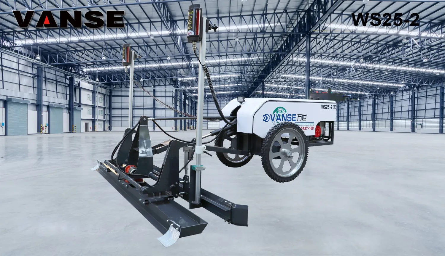
If the laser leveler is used improperly, it is easy to cause danger, especially if it rolls over, it is likely to cause casualties. Therefore, when using the leveler, you should always maintain the correct operation method, because only in this way can the safety of the laser leveler be guaranteed to the greatest extent, and the construction quality of the leveler can be well exerted. Please see the following for the correct operation method.
◀ Before the laser leveler moves, check the road conditions, remove obstacles on the road, keep irrelevant personnel away from the leveler, and then retract the telescopic arm to start.
◀ Check the direction of travel, determine the position of the drive wheel, and then honk the horn, and the laser leveler will start to move slowly.
◀ When reversing the laser leveler, estimate the space behind the car in advance. If the blind spot is too large, ask a special person to direct and coordinate behind.
◀ The driver controls the walking speed according to the road conditions. When walking on an open flat ground, you can select "1" gear, and the walking speed of the laser leveler will automatically increase or decrease according to the working pressure of the hydraulic walking circuit; when going up and downhill, you can select "0" gear, and the laser leveler will walk at a low speed and high torque.
◀ Try to choose a flat road when the laser leveler is walking.
◀ Avoid walking the leveler in water as much as possible. If you must wade, remember to explore the water depth and the soft and hard platform of the bottom of the water in advance. It is not suitable to walk if the underwater silt is too deep or the water surface exceeds the wheels
The above is the correct operation method of the laser leveler. I hope you can get some substantial reference value from this article. If you have other questions, please feel free to consult us at any time, and we will answer them one by one.
Thanks to All the Friends Who Support and Trust Shandong Vanse Machinery Technology Co., Ltd.
If you want to know more about Shandong Vanse Machinery Technology Co., Ltd. or have any questions, please feel free to contact us:
Our Factory
Shandong Vanse Machinery Technology Co., Ltd.








Share this article

About the Author: Shandong Vanse Machinery Technology Co., Ltd.
Shandong Vanse Machinery Technology Co., Ltd. is a high-tech manufacturer specializing in concrete construction machinery, including laser screeds and related equipment. The company integrates R&D, production, and global sales, with products exported to over 60 countries and widely used in infrastructure projects worldwide.
Previous Post
Next Post
Related Articles
You Might Also Like
Main methods for leveling concrete pavement
– Working principle: The laser concrete leveler uses the laser beam emitted by the laser transmitter as the reference plane, receives the laser signal through the laser receiver, and automatically controls the scraper height of the leveler. During the leveling process, the scraper of the leveler is raised and lowered according to the height of the laser reference plane to accurately level the concrete, which can effectively control the flatness and levelness of the road surface. – Operation points: First, the laser transmitter should be reasonably arranged at the construction site to ensure that the laser beam it emits can cover the entire construction area and is not blocked by obstacles. Then, the operator drives the leveler at a constant speed on the concrete, and the machine will automatically adjust the scraper height according to the laser signal to level the concrete. During the construction process, pay attention to the working status of the laser receiver and the leveling effect of the machine. If there is any abnormality, stop the machine in time for inspection and adjustment. At the same time, for corners that are difficult for the leveler to reach, manual assistance is still required. – Working principle: The paver evenly distributes concrete on the roadbed through the spiral distributor, and uses the vibrator to compact the concrete, forming a preliminary flat road surface during the process. – Operation points: Before construction, the paver parameters, such as the spiral distributor height, vibration frequency and amplitude, need to be adjusted according to the width and thickness of the road surface. During construction, the paver should be kept moving at a constant speed to ensure that the concrete paving thickness is uniform, thus laying the foundation for subsequent road leveling work. – Working principle: The vibration beam relies on its own vibration to squeeze and compact the aggregate particles in the concrete, and vibrate the cement mortar on the surface, so as to further level the road surface and improve the density. – Operation points: When using, the vibration beam needs to move slowly along the concrete road surface, and the vibration frequency and walking speed should be reasonably adjusted according to the slump of the concrete and the road surface conditions. For local uneven areas, the vibration beam can be manually assisted to carry out key treatment. – Working principle: The disc or blade of the trowel squeezes and smears the concrete surface when rotating, making the surface smoother and more compact, and improving the density and wear resistance. – Operation points: The surface should be troweled after the water on the concrete surface is slightly dry, and the appropriate trowel operation speed should be selected according to the coagulation of the concrete. For large-area pavement, a driving trowel can be used to improve efficiency, and narrow areas such as corners can be carefully processed with a hand-held trowel. – Working principle: Construction workers use wooden trowels, iron trowels and other tools to carefully trim the pavement with experience and feel, and deal with local uneven areas that are difficult for equipment to take care of. – Operation points: Mainly fine-tune the corners of the pavement, around the construction joints, and the traces left by the equipment, requiring construction workers to be skilled and able to accurately judge and deal with uneven areas to achieve higher flatness requirements.How to control power trowel blades speed to avoid super flat floor cracks?
Controlling power trowel speed is a delicate balancing act between compaction and friction. If the blades spin too fast too early, they create surface tension and heat that lead to "map cracking" or "crazing." To maintain an ultra-flat (FF) rating while preventing cracks, follow these speed and pitch protocols: The goal here is to break down the ridges left by the laser leveling and consolidate the surface without sealing it prematurely. Speed Setting: Low to Medium (50–80 RPM). * Why: High speeds at this stage can create "rotational shear," where the top layer of concrete is moved faster than the base, causing delamination or plastic shrinkage cracks. Technique: Use float pans (large metal disks) attached to the blades. Keep the blades completely flat. If you spin too fast with pans, you risk "throwing" the machine or creating a wavy surface that ruins your flatness. Once the bleed water has disappeared and the concrete can support the weight of the operator with only a 1/8" footprint, you move to the first "finishing" passes. Speed Setting: Medium (80–110 RPM). The "Crack Prevention" Fix: As you increase speed, you must slightly increase the pitch (angle) of the blades. This reduces the surface area of the blade in contact with the concrete, which lowers the friction-generated heat. Observation: If you see the surface "tearing" or small "chicken-wire" cracks appearing, your RPM is too high for the current moisture content. Slow down immediately. This is where you achieve that "mirror" finish. However, this is also the highest risk zone for "burnish cracks." Speed Setting: High (120+ RPM). Setting the Blades: Tilt the blades to a sharp angle. This puts maximum pressure on a small area to densify the surface. The Danger: If the blades are spinning at high RPM on a surface that is getting too dry, the friction generates localized heat. This causes the top 1/16" of the slab to expand and then rapidly contract, leading to thermal cracking. The Correction: If the concrete is "ringing" (making a high-pitched metallic sound) and looks scorched, ease off the throttle. Stage Blade Pitch Recommended RPM Goal Floating (Panning) Flat (0°) 50 – 80 Remove ridges; Consolidate Initial Finish Slight (5° – 10°) 80 – 110 Close the pores Final Burnish High (20°+) 120 – 150 Densify and shine The biggest mistake is staying at high RPM for too long on a "hot" (fast-setting) day. As the concrete loses moisture, it becomes more abrasive. Abrasive concrete + High RPM = Blistering and Cracking. Quick Correction: If you notice the surface drying too fast for your machine speed, apply a finishing aid (evaporation retardant). This lubricates the blades and allows you to maintain higher speeds without tearing the surface. Would you like me to explain how to coordinate the laser leveling passes with the trowel timing to ensure the edges don't dry out before the center? Contact us NOW Note: The parameters provided in this document are for reference only and are not mandatory. Due to differences in technical characteristics between different brands and models of laser levelers, please consult the manufacturer for a suitable solution before actual operation. This reference document assumes no responsibility for any issues arising from failure to follow the manufacturer's instructions.What are the characteristics of concrete laser leveling machine?
Concrete leveling machine is a kind of equipment widely used in the field of concrete construction. Its main features include the following aspects: High efficiency and efficient leveling: The concrete leveling machine can level the concrete surface quickly and efficiently, and can complete a project volume of 200 to 600 square meters per hour, which is more efficient than traditional manual leveling. Good flatness and high precision: The concrete leveling machine can provide precise elevation control and level adjustment. The concrete leveling machine can achieve a flatness of 3 mm/3 meters, and the elevation difference within 1000 square meters is less than 20 mm. , smoother than traditional manual leveling, effectively ensuring the quality of construction. Strong adaptability: The concrete leveler can level different types of concrete, such as sand, gravel, pebbles, etc., and can quickly complete the leveling work on the leveler. Reduce costs: Using a concrete leveler can reduce labor costs and improve construction efficiency. It can also reduce the use of materials, thereby reducing construction costs. High construction quality and high reliability: The concrete leveling machine adopts advanced mechanical structure, which has high reliability and can also ensure the quality of construction. It can significantly improve the flatness of the ground. The ground constructed by laser leveling machine and traditional method were tested at 22 points (one point every 5 meters × 4 meters). The average flatness values were 1.3 mm and 4.1 mm respectively. Laser leveling machine, etc. The leveling quality of the equipment is more than three times higher than that of traditional methods. The use of laser leveling machines can reduce a large number of construction joints, reduce concrete slump, and ensure concrete strength, making the ground more integrated and less prone to cracks. Simplified process and high safety: The operation of the concrete leveling machine is very simple and safe to use. It can save the formwork process. The concrete leveling machine is equipped with 6 to 10 people in a single shift and can complete a project volume of more than 3,000 square meters. It is more efficient than traditional Manual leveling is more convenient and can greatly reduce safety hazards caused by manual operations. Easy maintenance: The maintenance of the concrete levelinger is relatively simple. You only need to regularly check the lubricating oil, clean the machine body, etc. In short, the concrete leveling is an efficient, precise, adaptable, reliable, safe and easy-to-maintain equipment that has been widely used in the field of concrete construction.