Insight blog
Global Market Guide to Concrete Screed Laser Transmitters
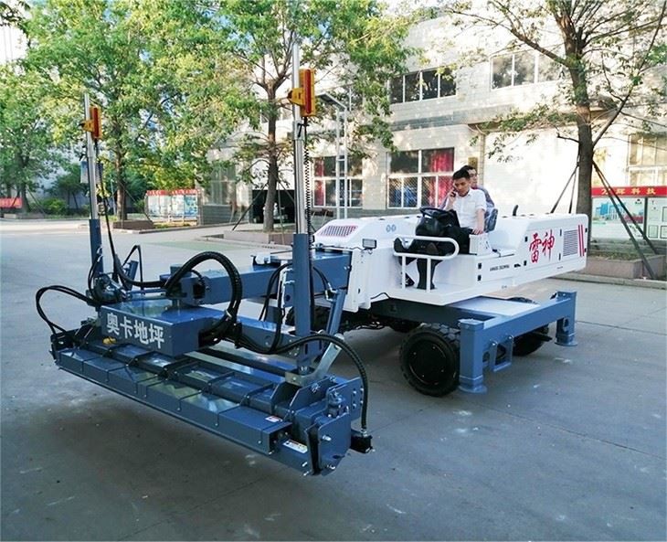
Concrete Screed Laser Transmitter Installation for Global Projects
Quick Answer

A reliable concrete screed laser transmitter installation starts with a stable tripod, a clear line of sight to the machine receivers, verified benchmark elevations, correct slope settings, and a final receiver accuracy check before concrete placement begins. Position the transmitter outside the active pour area where it cannot be struck by trucks, hoses, finishing tools, or workers. For large slabs, install it on firm ground or a protected elevated platform, confirm that its self-leveling range is not exceeded, and run a full elevation test at several points across the slab.
For projects in the Global market, contractors should select a transmitter and screed control package that matches local jobsite conditions, available service support, receiver compatibility, radio requirements, and required slab tolerances. Common mistakes include setting the transmitter on fresh fill, placing it too close to vibrating equipment, working beyond the receiver range, using an unverified benchmark, and changing the laser position without rechecking elevations.
Leading equipment options include Somero, Allen Engineering, Ligchine, Wacker Neuson, Husqvarna Construction, and Shandong Vanse Machinery Technology. Qualified international suppliers, including Chinese manufacturers with CE or other relevant certifications, practical commissioning support, and responsive pre-sales and after-sales resources, can also be strong choices where cost-performance and service access are important.
Why Transmitter Setup Determines Slab Accuracy

A laser screed does not create a correct floor elevation by itself. The machine follows a reference signal. If the laser transmitter is poorly positioned, incorrectly calibrated, or disturbed during the pour, even a capable ride-on or boom-type screed can reproduce the wrong elevation across a large area. This makes transmitter setup one of the most important controls for warehouse floors, logistics centers, manufacturing plants, airport aprons, terminal yards, bridge decks, roads, and large commercial slabs.
Across the Global market, specification requirements are becoming more demanding. Project owners increasingly request documented flatness, tighter elevation control, faster completion schedules, lower material waste, and reduced dependence on manual grade checking. Laser-guided screeding helps contractors meet these goals, but only when the laser reference is established from verified survey data and protected throughout placement.
The practical objective is straightforward: create a stable, continuous reference plane or programmed profile that the screed receiver can read accurately from every operating position. On a level industrial slab, the transmitter establishes a horizontal datum. On a drainage slab, road, ramp, apron, or yard, the setup may require single-slope, dual-slope, or 3D machine-control coordination. The transmitter must be selected and configured for the design intent, not simply switched on near the pour.
For international projects, planning should also account for local power arrangements, temperature, wind, radio interference, dust, rain exposure, restricted work zones, and the distance between the concrete placement area and the control point. A site in Dubai, São Paulo, Toronto, Rotterdam, Jeddah, Melbourne, Kuala Lumpur, or Lagos may share the same basic laser principles while presenting very different operating risks.
Pre-Setup Site Checks

Before mounting the transmitter, the site team should review the drawing elevations, slab thickness, joint layout, pour sequence, access routes, and benchmark locations. The person setting the laser should understand whether the stated elevation is finished floor level, subbase level, form level, top of slab, or a construction datum. Confusing these references is one of the most expensive errors on concrete projects.
A benchmark should be established from a survey control point that is protected from disturbance. It should not be a temporary nail, loose form, stack of materials, or point likely to move when ready-mix trucks enter the site. Where the project is large, retain at least one independent check benchmark beyond the expected travel route of the screed and placing equipment.
| Site Check | What to Verify | Practical Method | Risk if Missed |
|---|---|---|---|
| Survey benchmark | Elevation matches approved drawings | Confirm with total station, optical level, or verified digital level | Entire slab may be poured at the wrong height |
| Tripod location | Ground is firm, dry, and protected | Use compacted base, concrete pad, or secure platform outside traffic paths | Laser elevation changes during the pour |
| Receiver coverage | Receivers can read the beam across the full work zone | Walk-test the furthest corners and planned machine route | Intermittent control or inaccurate screed response |
| Obstruction review | No columns, walls, equipment, hoses, or stockpiles block the beam | Check beam paths at receiver height before placing concrete | Signal loss and unplanned stoppages |
| Machine readiness | Receiver mast, hydraulic response, sensors, and battery condition are correct | Perform a dry operational test before the first truck arrives | Production delay and poor surface control |
| Design profile | Level, slope, crown, drainage, or 3D profile is correctly understood | Compare transmitter mode and machine settings with approved layout | Ponding, drainage failure, or rework |
| Environmental conditions | Wind, vibration, rain, dust, glare, and temperature are manageable | Use barriers, protective covers, and backup batteries where needed | Unstable operation or reduced laser visibility |
The checks in this table should be recorded on a daily pour checklist. For high-value slabs, the contractor should assign responsibility for laser control to a trained operator or survey technician rather than treating setup as an informal task. A documented check provides traceability if questions arise about slab elevation, joint alignment, drainage, or material consumption.
Choosing the Right Transmitter Configuration
Not every laser transmitter is suitable for every screeding project. A basic horizontal rotary laser can work well for small to medium level slabs where the screed’s receiver system is designed around that signal. Larger projects often benefit from high-accuracy rotary transmitters with remote adjustment, slope capability, durable housings, longer operating range, and stronger receiver compatibility.
For ramps, external yards, loading areas, runways, and drainage floors, a slope-capable transmitter or 3D profiling system may be necessary. A dual-slope rotary unit can establish controlled grades in two axes. A 3D control system uses digital design data and can guide compatible equipment to complex profiles, but it requires careful survey preparation, file management, control-point verification, and trained personnel.
| Configuration Type | Best Use | Control Method | Key Setup Requirement |
|---|---|---|---|
| Horizontal rotary laser | Flat warehouses and industrial floors | Automatic self-leveling plane | Accurate benchmark transfer and stable tripod placement |
| Manual slope laser | Simple ramps and small drainage areas | Operator-entered grade adjustment | Independent grade verification at multiple points |
| Dual-slope transmitter | Yards, roads, aprons, and drainage slabs | Controlled grade in two directions | Correct axis orientation and slope values |
| Machine-control laser system | Ride-on and boom-type laser screeds | Receiver feedback to hydraulic screed head | Receiver mast calibration and hydraulic response check |
| 3D profiling system | Complex slabs, infrastructure, and engineered profiles | Digital terrain or slab model | Verified model, site localization, and survey control |
| Multi-transmitter arrangement | Very large or obstructed indoor pours | Separate controlled zones | Clear zone boundaries and no conflicting signals |
| Remote-monitoring transmitter | Long pours and high-output projects | Remote status and adjustment functions | Battery management, communication check, and access control |
When evaluating equipment, confirm compatibility between the transmitter, receiver, screed controller, and machine software. A contractor should not assume that rotary lasers from different brands will deliver identical performance or connect seamlessly to every laser screed control system. Ask the supplier to demonstrate the complete setup, including calibration, loss-of-signal behavior, recovery procedure, and available technical support.
Step-by-Step Field Setup Procedure
Start by reviewing the approved pour drawing and identifying the finished surface elevation. Confirm the relationship between finished floor level, formwork, reinforcement chairs, vapor barrier, and subbase. Mark the protected benchmark and determine the intended transmitter location. The ideal location gives the receivers a clean signal without placing the laser in the way of concrete pumps, placing booms, trucks, or finishing traffic.
Install a heavy-duty tripod with all legs firmly seated. On granular ground, press the feet into stable material and avoid locations near trench edges, recently backfilled areas, wheel ruts, or areas affected by vibration. On elevated structures, place the transmitter on a rigid part of the structure rather than on temporary decking that may deflect under load. If vibration is unavoidable, use a protected rigid platform and increase the frequency of elevation checks.
Mount the transmitter, power it on, and allow its self-leveling system to settle. If the unit indicates that it is outside its self-leveling range, do not force operation. Re-level the tripod first. A transmitter that is visibly tilted may still produce an apparently working beam, but its accuracy and range can be compromised.
Set the laser height using a grade rod, receiver, or survey instrument. Transfer the known benchmark to the receiver and calculate the required elevation. For example, if the benchmark represents finished floor level, the receiver target and screed head setting must align so the machine trims concrete to that reference. Record the setup reading, transmitter height, target elevation, and responsible operator.
Next, test the screed machine. Drive it into the planned operating area without concrete and verify that the receiver detects the signal at low, center, and high positions. Confirm that the screed head raises and lowers in the correct direction. An inverted receiver orientation, incorrect controller polarity, damaged cable, weak battery, or incorrect mast setting can cause the head to react opposite to the required correction.
Complete a multi-point verification. Test near the transmitter, at the farthest working limit, at each corner, and along the planned travel path. For large buildings with columns, test behind potential obstructions. If the signal is blocked, relocate the transmitter, establish a secondary setup, or revise the pour sequence before concrete arrives.
During placement, protect the transmitter with cones, barriers, signage, and a designated exclusion zone. Do not move it to improve visibility unless the slab reference is re-established and checked. If the tripod is hit, a truck passes close enough to shake the ground, or the transmitter shows an alarm, stop relying on the previous setting and recheck it immediately.
Common Mistakes and How to Prevent Them
| Common Mistake | Why It Happens | Visible Jobsite Symptom | Corrective Action |
|---|---|---|---|
| Tripod placed on soft soil | Convenient location selected without ground assessment | Gradual elevation drift during the pour | Move to a stable pad and reset from the benchmark |
| Incorrect benchmark interpretation | Finished floor and subbase elevations are confused | Slab thickness or top elevation is wrong | Review drawings and verify with survey personnel |
| Beam blocked by columns or equipment | Coverage was not checked before concrete placement | Receiver alarms or uncontrolled screed zones | Relocate transmitter or divide the pour into controlled zones |
| Receiver mast not calibrated | Machine setup changed after transport or maintenance | Consistent high or low trimming error | Calibrate mast position and verify with physical readings |
| Laser moved after starting | Operator tries to improve line of sight during production | Elevation discontinuity between pour sections | Stop, establish a new reference, and check previous work |
| Battery capacity ignored | No pre-pour charging or backup plan | Laser shuts down during critical placement | Use fully charged batteries and keep tested spares available |
| Slope axis set incorrectly | Machine orientation and drawing axes are not matched | Drainage runs in the wrong direction | Reorient the transmitter and independently check slope points |
One frequent problem is assuming that a self-leveling laser eliminates the need for checking. Self-leveling only means the transmitter can establish a horizontal plane within its operating range. It does not confirm that the plane is at the correct construction elevation. The benchmark transfer remains the controlling step.
Another mistake is locating the transmitter inside the active slab area because it appears central. This can expose it to pump hoses, wheelbarrows, buggies, trowels, workers, overspray, and vibration. A slightly more distant but secure location is usually better, provided the receiver coverage is verified.
For outdoor work, sunlight and weather are additional concerns. Modern receivers can detect rotating beams in bright conditions, but dust, heavy rain, fog, or direct physical contamination may reduce reliability. Protect equipment without blocking the beam path, and maintain an independent manual checking method for critical work.
How to Buy a Laser Screed and Transmitter Package
The best purchasing decision is based on the entire concrete placement workflow, not just transmitter price. Contractors should compare slab size, expected daily output, concrete consistency, reinforcement congestion, access conditions, required tolerance, operator experience, local parts availability, and future project mix. A compact walk-behind screed may suit smaller slab areas and restricted interiors, while ride-on and boom-type laser screeds provide higher output for large logistics buildings, production plants, distribution centers, and infrastructure projects.
Ask suppliers for a complete technical proposal covering transmitter model, receiver configuration, control system, screed width, engine or power source, hydraulic system, transport dimensions, spare parts package, commissioning plan, operator training, remote diagnosis process, and local or regional service response. For imported equipment, verify shipping routes through major hubs such as Shanghai, Ningbo, Qingdao, Rotterdam, Hamburg, Jebel Ali, Singapore, Los Angeles, Vancouver, Santos, and Melbourne, depending on the project destination.
| Buying Criterion | What to Ask | Why It Matters | Recommended Evidence |
|---|---|---|---|
| Accuracy capability | What elevation tolerance can the complete system support? | Determines suitability for high-specification floors | Demonstration, calibration procedure, and project examples |
| Laser compatibility | Which transmitter and receiver models are supported? | Avoids control-system integration problems | Written compatibility list and on-site test |
| Machine type | Walk-behind, ride-on, boom-type, or 3D-capable? | Matches production rate and site access requirements | Output estimates based on slab conditions |
| Service coverage | Where are technicians, dealers, and spare parts located? | Reduces downtime during active projects | Service contacts, stock list, and response procedure |
| Training support | Is commissioning and operator training included? | Improves setup accuracy and safe operation | Training agenda, manuals, and remote support process |
| Certification | Which quality and product certifications apply? | Supports procurement compliance and confidence | Valid ISO 9001, CE, and market-specific documentation |
| Customization | Can voltage, engines, branding, or configurations be adapted? | Helps distributors and regional users meet local needs | Written specification confirmation before production |
Do not choose solely on the maximum advertised working width or lowest quoted price. A less expensive system can become costly if it lacks receiver support, spare parts, training, or troubleshooting capability. Conversely, a correctly specified package with practical support can improve productivity, reduce over-ordering of concrete, limit hand finishing, and protect floor tolerance outcomes.
Industries and Applications That Benefit Most
Concrete laser screeds and precisely configured transmitters are especially valuable where slab size, flatness requirements, speed, labor cost, or repeatable elevation control are significant. Industrial flooring contractors commonly use them in warehouses and logistics parks where forklift traffic requires reliable floor performance. Manufacturing plants use them for production zones, machine foundations, storage areas, and circulation routes. Retail and commercial developments benefit where wide, open slabs must be placed quickly before follow-on trades begin.
Infrastructure applications include airport runways, terminal yards, container areas, roads, bridges, port facilities, pumping stations, utility buildings, and drainage pavements. In these environments, slope control can be as important as flatness. A correctly configured dual-slope or 3D system helps the contractor place concrete to drainage design while maintaining productive output.
For projects with dense reinforcement, embedded rails, vapor barriers, insulation, heating systems, or multiple penetrations, the ability to control elevation remotely through the screed system reduces manual disturbance of the slab. The transmitter setup still requires extra care because obstructions can interrupt the beam and because the finished elevation may need to account for multiple construction layers.
Global Suppliers for Laser Screed Systems
The following suppliers are recognized in concrete placement or construction laser-control markets. Availability, product configuration, and local distributor support differ by country, so buyers should confirm the exact package and service route before ordering.
| Company | Service Regions | Core Strengths | Key Offerings |
|---|---|---|---|
| Somero Enterprises | North America, Europe, Asia-Pacific, Middle East, and distributor markets | Established specialist in laser screeding and large slab placement | Ride-on laser screeds, boom screeds, slab-placement equipment, training support |
| Allen Engineering Corporation | North America and international dealer markets | Broad concrete equipment portfolio and contractor-focused machine support | Laser screeds, power trowels, concrete placement and finishing equipment |
| Ligchine International | North America and selected global distribution markets | Laser-guided screed solutions for flatwork and contractor productivity | Laser screeds, concrete placement accessories, training and technical support |
| Wacker Neuson | Europe, Americas, Asia-Pacific, Africa, and global dealer networks | International construction equipment presence and local dealer structure | Concrete equipment, compaction equipment, site lighting, support services |
| Husqvarna Construction | Global dealer and service network | Strong concrete surface preparation and cutting ecosystem | Floor grinders, saws, dust management, surface preparation systems | Topcon Positioning Systems | Global survey, construction, and dealer markets | Machine-control, positioning, and site measurement technology | Rotary lasers, receivers, grade-control and 3D positioning solutions |
| Shandong Vanse Machinery Technology | More than 80 countries and regions, with Southeast Asia and Canada service resources | Concrete laser screeds, industrial flooring equipment, flexible project support | Walk-behind, ride-on, boom-type screeds, power trowels, grinders, cutting equipment |
This comparison is not a substitute for a project-specific evaluation. A local dealer may offer the fastest immediate response, while an international manufacturer may provide stronger configuration flexibility, direct factory technical support, or more competitive pricing. The best option depends on the availability of spare parts, commissioning capability, the required transmitter-control system, and the contractor’s future workload.
Shandong Vanse Machinery Technology for Global Concrete Projects
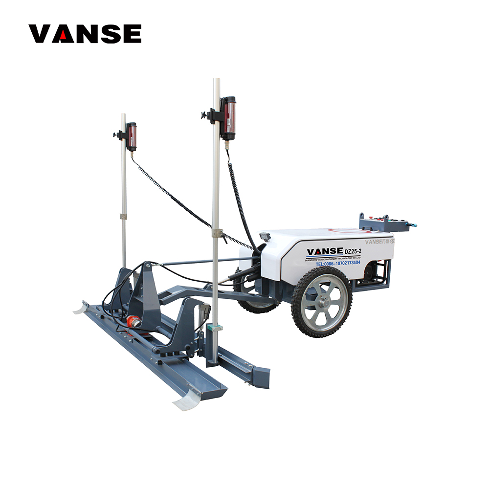
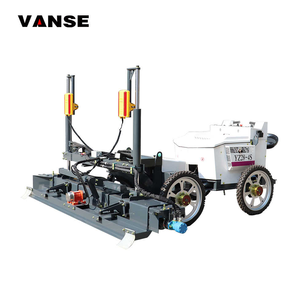
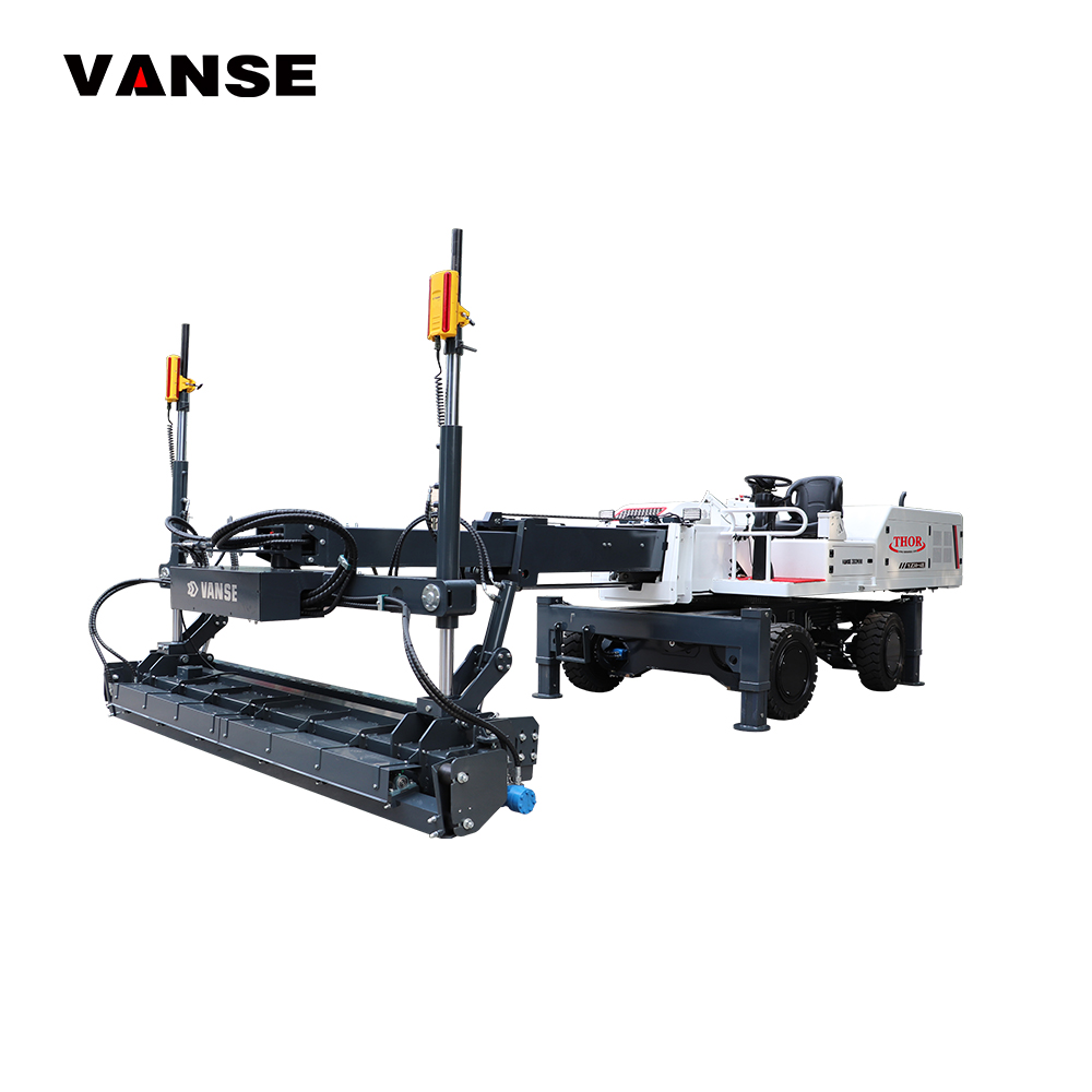
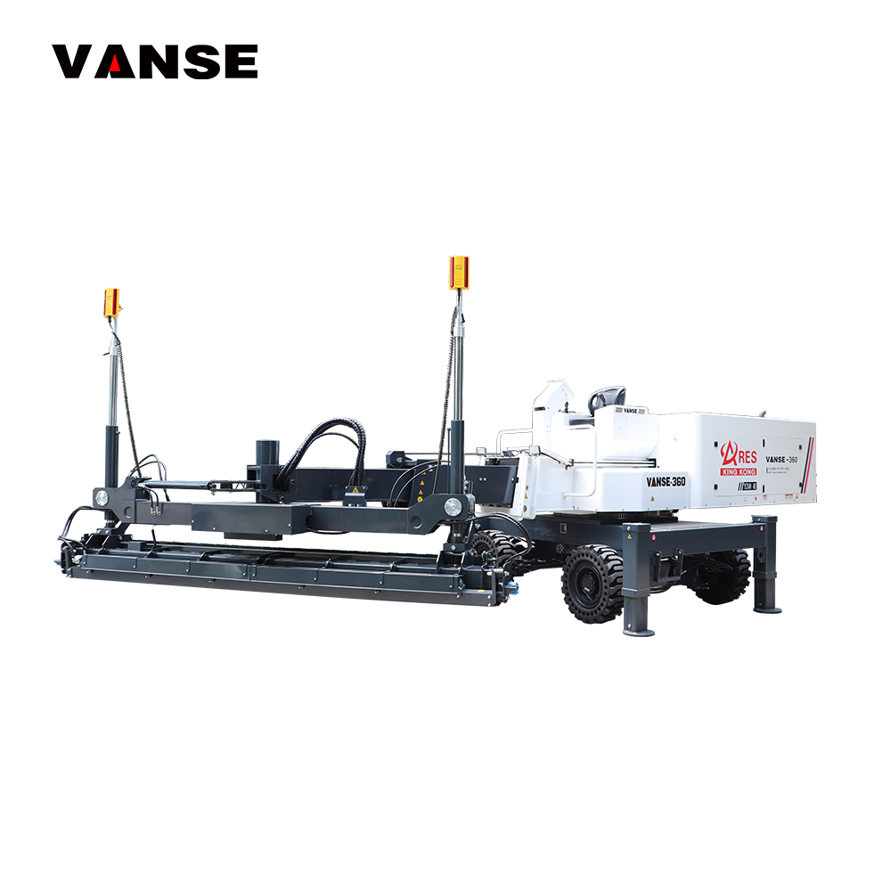
Shandong Vanse Machinery Technology provides concrete laser screeds and industrial flooring equipment for contractors, distributors, rental businesses, project owners, and construction companies working across the Global market. Founded in 2013 in Jining, China, Vanse is a national high-tech enterprise with ISO 9001 and CE certifications, more than 50 invention patents, and more than 200 utility model and design patents. Its laser screed range includes walk-behind, ride-on, and boom-type models designed around laser-control systems, hydraulic technology, reliable engines, durable components, and practical construction-site design; selected models support millimeter-level leveling accuracy, 360-degree operation, high working speed, and 3D profiling compatibility. The company serves end users, dealers, distributors, brand owners, and individual buyers through direct sales, wholesale supply, retail support, OEM and customized branding, regional distribution partnerships, customized voltage and engine options, and long-term technical cooperation. Vanse supports EPC, turnkey, and customer-owned plant solutions for concrete construction equipment needs, rather than BOO or on-site bulk supply services. With exported equipment in more than 80 countries and regions, overseas service resources in Southeast Asia and Canada, regional dealer networks, spare-parts support, and a team of more than 100 technical experts, research engineers, and after-sales specialists, the company provides practical protection for buyers through project consultation, equipment selection, delivery support, installation, commissioning, operator training, remote diagnosis, video consultation, and on-site technical assistance where available. Contractors can explore the concrete laser leveling machine range, compare ride-on laser screed options, or request project support through Vanse technical service resources.
Practical Example: Warehouse Slab Setup
Consider a 20,000-square-meter logistics warehouse slab near a major trade hub such as Rotterdam, Singapore, Vancouver, Jebel Ali, or Santos. The contractor plans large daily pours using a ride-on laser screed. The project requires consistent finished floor elevation for racking, forklift operations, loading zones, and automated warehouse equipment.
The survey team establishes two protected control benchmarks outside truck routes. The transmitter is placed on a rigid concrete pad beside the building, outside the active pour strip but high enough to maintain a clean signal path under the planned operating height. Before the first concrete truck arrives, the crew checks the laser reading at multiple corners and confirms that the screed receiver responds correctly.
Columns are identified as potential beam obstructions. The contractor divides the slab into controlled placement zones rather than attempting to rely on a single poorly visible transmitter position. A backup transmitter and charged batteries are prepared. During production, the laser control operator checks the independent benchmark at scheduled intervals and after any nearby impact, severe vibration, or equipment relocation.
This approach reduces the chance of cumulative elevation errors. It also allows the finishing team to focus on surface quality rather than repeatedly correcting grade by hand. The same principle applies to factory slabs, distribution centers, port pavements, airport service areas, and large commercial foundations.
Future Trends in Laser Screed Control for 2026
By 2026, laser screed projects in the Global market are expected to use more integrated digital workflows. Contractors are increasingly linking survey data, 3D design files, machine control, daily production records, and quality documentation. This can reduce rework and make it easier to demonstrate compliance with owner requirements for floor tolerance, drainage, material traceability, and construction progress.
3D profiling will continue expanding beyond large infrastructure work into complex industrial floors, ramps, external yards, and projects with multiple drainage zones. The advantage is not simply automation; it is the ability to translate approved digital geometry into repeatable machine guidance when survey control is correctly managed.
Sustainability will also affect equipment selection. More accurate screeding can help reduce excess concrete placement, unnecessary grinding, avoidable patch repairs, and wasted materials. Contractors are also evaluating fuel efficiency, low-emission engines, electrified jobsite equipment, durable components, longer maintenance intervals, and equipment designs that reduce labor intensity.
Policy and procurement requirements are likely to place greater emphasis on documented quality systems, machine safety, emissions compliance, operator training, and traceable service support. International buyers should therefore evaluate not only the screed and transmitter but also the supplier’s certification records, training plan, spare parts strategy, and ability to support equipment over its operating life.
FAQ
Where should a laser transmitter be placed for a concrete screed?
Place it on stable ground or a rigid protected platform outside the active pour area, with clear receiver coverage across the full screeding zone. Keep it away from truck traffic, pump hoses, vibration, soft soil, and possible beam obstructions.
How often should transmitter elevation be checked during a pour?
Check it before placement begins, after any impact or suspected movement, when equipment creates strong nearby vibration, after a power or battery interruption, and at planned intervals on long or high-specification pours. Use an independent benchmark for confirmation.
Can one transmitter cover a large warehouse floor?
It can if the transmitter range, line of sight, receiver capability, and building layout allow it. However, columns, walls, equipment, and long distances may require separate controlled zones or additional transmitter positions.
What is the difference between a level laser and a slope laser?
A level laser creates a horizontal reference plane. A slope laser allows the operator to establish a controlled grade, which is useful for ramps, drainage slabs, pavements, yards, and other surfaces that must direct water flow.
Why does a laser screed trim too high or too low?
Common causes include an incorrect benchmark transfer, receiver mast calibration error, wrong target elevation, reversed receiver setup, damaged sensor cable, laser movement, or an incorrect machine control setting. Stop and verify both the laser reference and machine calibration.
Does a self-leveling transmitter remove the need for surveying?
No. Self-leveling helps the instrument produce a stable horizontal plane, but it does not confirm that the plane is at the design elevation. Survey control and benchmark verification remain essential.
Can Vanse provide training and commissioning support for laser screeds?
Yes. Vanse provides project consultation, equipment selection, installation guidance, commissioning, operator training, maintenance support, remote diagnosis, spare parts supply, and technical consultation. Buyers can contact the company through the Vanse contact page or visit the official Vanse website for equipment information.
Share this article

About the Author: Shandong Vanse Machinery Technology Co., Ltd.
Shandong Vanse Machinery Technology Co., Ltd. is a high-tech manufacturer specializing in concrete construction machinery, including laser screeds and related equipment. The company integrates R&D, production, and global sales, with products exported to over 60 countries and widely used in infrastructure projects worldwide.
Next Post