Technical Knowledge
How to evaluate the reliability and compatibility of laser receivers?

Evaluating the reliability and compatibility of a laser receiver can be carried out through the following aspects:
1. Durability test:
Through long-term running tests and tests in harsh environments, observe the performance changes and failure rates of the receiver to evaluate its reliability and stability.
2. Compatibility test:
By testing the matching degree between the receiver and lasers of different types and specifications, observe the output signal and performance indicators of the receiver to evaluate its compatibility.
3. Reliability analysis:
Conduct reliability analysis on the internal circuits, optical components and mechanical structure of the receiver, including but not limited to life test, failure rate test and failure mode analysis to evaluate its reliability.
4. Compatibility evaluation:
Evaluate the receiver's spectral response range, modulation frequency, polarization state and other characteristics to determine its compatibility with different types of lasers.
5. Production quality inspection:
Inspect the production quality of the receiver, including but not limited to appearance inspection, performance testing and environmental adaptability testing, to evaluate its reliability and compatibility.
6. Application case analysis:
Analyze the actual application cases of the receiver, including but not limited to application fields, usage environment and system configuration, to evaluate its reliability and compatibility.
In summary, evaluating the reliability and compatibility of a laser receiver requires comprehensive consideration of multiple aspects of testing and analysis. Through these evaluation methods, the performance and reliability of the receiver can be fully understood, providing strong guarantee for practical applications.


Thanks to All the Friends Who Support and Trust Shandong Vanse Machinery Technology Co., Ltd.
If you want to know more about Shandong Vanse Machinery Technology Co., Ltd. or have any questions, please feel free to contact us:
Our Factory
Shandong Vanse Machinery Technology Co., Ltd.








Share this article

About the Author: Shandong Vanse Machinery Technology Co., Ltd.
Shandong Vanse Machinery Technology Co., Ltd. is a high-tech manufacturer specializing in concrete construction machinery, including laser screeds and related equipment. The company integrates R&D, production, and global sales, with products exported to over 60 countries and widely used in infrastructure projects worldwide.
Previous Post
Next Post
Related Articles
You Might Also Like
What’s the impact of the laying direction of the steel mesh on the building structure?
Relationship with the direction of principal stress: The main function of the steel mesh is to bear the tensile force in the concrete structure. When the structure is stressed, the principal stress will be generated inside the concrete. The laying direction of the steel mesh should be consistent with the principal stress direction as much as possible, so that the tensile strength of the steel bars can be fully exerted and the bearing capacity of the structure can be effectively improved. For example, in a one-way slab, the load is mainly transmitted along the short span direction, and the direction of the principal tensile stress is also roughly along the short span direction. Therefore, the bottom steel mesh is usually arranged along the short span direction to resist the tensile force. Two-way stress situation: For a two-way slab, the spans in both directions are similar, and both bear a large load. The steel mesh in both directions must bear tensile force. At this time, the steel mesh should be arranged in a certain proportion according to the force size in the two directions, and is generally laid perpendicular to each other, so that the structure can have sufficient bearing capacity and good deformation performance in both directions. Control of crack direction: A reasonable laying direction of the steel mesh can guide the development direction of the crack, so that it develops in the direction with less influence on the structural force. For example, in concrete pavement, transverse reinforcement can limit the development of longitudinal cracks, while longitudinal reinforcement can restrain transverse cracks, thereby improving the integrity and durability of the pavement. Improving crack resistance: When the steel mesh is laid along the direction where cracks may occur, it can play a "bridge" role after the concrete cracks, withstand the tension on both sides of the cracks, and prevent the cracks from further expanding. For example, in the wall of a hydraulic structure, the horizontal and vertical steel meshes work together to effectively improve the wall's ability to resist cracks caused by factors such as temperature changes and concrete shrinkage. Protecting steel bars: The correct laying direction of the steel mesh helps to ensure the protective effect of concrete on the steel bars. The steel bars are wrapped in concrete to prevent them from rusting and corroding when exposed to the external environment. If the steel mesh is laid improperly, resulting in deviation in the position of the steel bars or uneven thickness of the protective layer, the steel bars are prone to rust under the action of external corrosive media, thereby reducing the durability of the structure. For example, in the basement structure of a building, the laying of the steel mesh should ensure that there is a sufficient and uniform concrete protective layer to prevent groundwater from corroding the steel bars. Uniform stress: Reasonable laying direction makes the steel mesh evenly stressed in the structure, avoiding premature destruction of concrete due to local stress concentration, thereby providing a stable protective environment for the steel bars and extending the service life of the structure. In short, the laying direction of the steel mesh is an important factor affecting the performance of the building structure. During the construction process, the laying direction of the steel mesh must be reasonably determined according to the stress characteristics and design requirements of the structure to ensure the safety, applicability and durability of the building structure.Diagnosis and solutions for a normal power trowel machine engine but unable to drive the power trowel disc (such as belt, clutch, etc.)
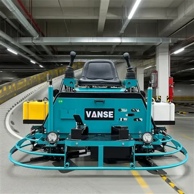
This is a common malfunction of the power trowel machine (also known as the gloss collector or polishing machine). The engine is normal (it can start and the speed sounds normal), but the brake is weak, does not rotate or rotates slowly. The problem must lie in the power transmission system. The following are systematic diagnostic steps and solutions, arranged in order from simple to complex and from outside to inside. Engine normal → The disc does not move/lacks power → Check the power transmission path External/Simple inspection → Drive belt system → Clutch system → Gearbox/main shaft Before disassembling the machine, rule out the following possibilities first Excessive load on the power trowel plate: The concrete has passed its optimal finishing time (final setting), and its strength is too high, causing the power trowel plate to be "stuck". Try lifting the machine or testing it on a less hard ground. The issue with the Angle of the power trowel blade: The installation Angle of the blade is too "flat" (the Angle with the ground is too small), resulting in huge resistance. Adjust the blade to an appropriate Angle (usually 5 to 15 degrees to the ground). Foreign object jamming: Check whether the area beneath the power trowel plate and around the main shaft are jammed by hard objects such as cement blocks or steel bar heads. The polishing machine usually uses a belt to transfer the engine power to the clutch or gearbox. Symptoms The engine makes a loud noise when idling, and when wiping the disc, it rotates intermittently or doesn't move at all. When the machine is working, a burnt smell can be detected (due to the belt slipping and rubbing). The speed of the power trowel disc is significantly lower than that of the engine, and it is weak. Diagnostic steps Shutdown inspection: Turn off the engine and check if the belt is broken, fallen off or severely worn (with cracks on the side and a shiny back). Tightness check: Press the middle of the belt forcefully with your fingers. The normal deflection should be around 10-15mm. If it is too loose, it will slip; if it is too tight, it will accelerate wear and cause damage to the bearing. For moderate inspection: Check whether the engine pulley and the driven pulley are on the same plane. Misalignment can cause abnormal wear and detachment of the belt. Solution Replace the belt: Be sure to use the original factory or the specified model belt. Adjust the tightness: Loosen the fixing bolts of the engine base, move the engine position to adjust the tension of the belt, and then retighten the bolts. Calibration and alignment: Inspect and adjust the installation base of the engine or driven wheel. Centrifugal clutches are commonly used in power trowels. When the engine reaches a certain speed, the clutch block is thrown out under the action of centrifugal force and combines with the clutch cover to transmit power. Symptoms When the engine is running at low speed, the disc does not rotate. At high speed, it may engage but weakly, or it may not engage at all. When the engine speed changes, there is a "clattering" sound or a metallic friction sound inside, but the power cannot be transmitted out. Diagnostic steps Visual inspection (disassembly required) : Remove the clutch protection cover or the wiping plate. Check the clutch friction block Wear: Whether the friction plate has worn to its limit (exposed metal or extremely thin thickness). Oil stains: Whether contaminated by lubricating oil or grease (causing slippage). Detachment: Whether the friction plate has fallen off from the horseshoe. Check the clutch spring Whether the spring is broken, fallen off or fatigued and deformed. Insufficient spring force can cause the clutch block to fail to be flung out or retracted at the correct speed. Check the inner wall of the clutch cover (drum) Whether the inner wall is smooth or has deep grooves. Oil stains and grooves can both cause slipping. Solution Cleaning: Thoroughly clean all oil stains with carburetor cleaner. Replacement: Replace the worn clutch friction blocks and broken/deformed springs in a complete set. It is recommended that the friction blocks be replaced in pairs. Repair/Replacement: If there are deep grooves on the inner wall of the clutch drum, the assembly needs to be repaired or replaced with a lathe. If both the belt and the clutch are functioning properly, the problem may extend to the final stage. Symptoms The engine and clutch work normally, but the main shaft doesn't rotate at all. When the machine is running, there is an abnormal noise (creaking, clicking) from the gearbox. The main shaft can be shaken by hand and there is a distinct gap. Diagnostic steps Check the gear oil: Whether the gearbox is short of oil or has metal debris (the oil is grayish-white). Lack of oil can cause gears and bearings to burn out. Check the gears: Open the gearbox to inspect whether the planetary gears or spur gears have broken teeth or severe wear. Check the bearings: Inspect whether the upper and lower bearings of the main shaft are cracked or stuck. Rotate the main shaft by hand to feel if there is any jamming or abnormal noise. Check the splines/keyways: Whether the splines of the main shaft connected to the trotter or the keyways of the clutch output are worn flat, which may prevent power transmission. Solution Change gear oil: Add gear oil of the specified type and volume. Replace damaged parts: Replace damaged gears, bearings or splined shafts. This usually requires professional maintenance personnel to carry out. Serial number Inspection site Possible reasons Solution Priority 1 External and Load The ground is too hard, the blade Angle is poor, and foreign objects are stuck Adjust the Angle and clear the foreign objects High 2 Drive belt Fracture, loosening, wear, misalignment Replace, adjust the tension and correct the alignment High 3 Centrifugal clutch Friction block wear/oil stains, spring breakage Clean and replace the friction blocks and springs High 4 Gearbox Lack of oil, gear damage, bearing damage Refuel and replace gears/bearings In the 5 Main shaft/spline The splines are ground flat and the main shaft is bent Replace the main shaft Low Before any maintenance, be sure to turn off the engine and unplug the high-voltage wires of the spark plugs to prevent accidental start-up. Wait until the engine and exhaust components have completely cooled down before operating. When disassembling, pay attention to the sequence of the parts and take photos for record. When reinstalling, the key bolts need to be tightened as required by the torque. If you are not familiar with the mechanical structure, it is recommended that you contact professional equipment maintenance personnel for handling. In the above order, the vast majority of problems with the power trowel that are "powerless but unable to be utilized" can be identified and resolved. The most common and top-priority items to be inspected are belts and clutches. Note: The parameters provided in this document are for reference only and are not mandatory. Due to differences in technical characteristics between different brands and models of laser levelers, please consult the manufacturer for a suitable solution before actual operation. This reference document assumes no responsibility for any issues arising from failure to follow the manufacturer's instructions.Quality Control And Precautions In The Construction Process Of Concrete Laser Leveling Machine
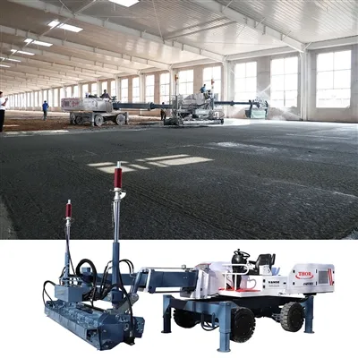
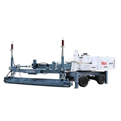
Quality Control And Precautions In The Construction Process Of Concrete Laser Leveling Machine Concrete laser leveling machine is an indispensable equipment in construction machinery, and it is indispensable in the construction of building floors. Doing the following points well during construction will have a great effect on improving the productivity and construction quality of the concrete laser leveling machine. 1. Line setting and leveling on the wall (column): Since the laser leveling machine on the side of the wall cannot be touched, manual leveling is required within 40 cm along the side of the wall (formwork), so line setting is required as a reference for manual leveling . 2. Set up formwork (steel formwork is recommended) along the scope of pouring on the same day, reserve holes for dowel rods, and control the elevation of the formwork to avoid large deviations in the flatness of the joints of different warehouses. 3. Set templates or thin sheets along the walls, equipment foundations, columns, etc. (thickness and position are determined according to design requirements), and leave separation joints to avoid cracking of the concrete floor. 4. Laser transmitter erection: (1) The laser transmitter should be erected at the best position, and there should be no clips to be tightened; (2) There should be no large vibration sources around; (3) Reasonably set the concrete paving direction and leveling direction, and determine a reasonable construction walking route of the leveling machine to avoid leveling blind spots. (4) Feeding: The concrete conveying speed should be guaranteed to be a certain amount, and the feeding speed should be uniform, and the pause interval should be reduced in the middle to prevent cold joints and affect the progress of the project. The slump and initial setting time of the concrete sent to the site each time must be consistent. The concrete slump should be controlled at 14~16cm, and the initial setting time should be controlled at about 3 hours. Note: Some content of this quality control is for reference only, and the actual construction should be formulated according to the floor design requirements and the characteristics of the construction site.