Technical Knowledge
How to optimize the performance & stability of laser receivers?
Optimizing laser receiver performance and stability requires consideration of the following aspects:
1. Select high-performance optical components:
Selecting high-quality optical components can reduce problems such as scattering, reflection, and aberration in the optical path, thereby improving the sensitivity and stability of the receiver.
2. Improve the detection efficiency of the receiver:
Using efficient photoelectric detectors can improve the detection efficiency of the receiver, thereby improving the sensitivity and dynamic range of the receiver.
3. Optimize the optical system design:
Optimizing the optical system design can reduce the beam divergence angle and improve the beam quality, thereby reducing the noise and dynamic range limitations of the receiver.
4. Add temperature control and compensation mechanisms:
By adding temperature control and compensation mechanisms, the impact of ambient temperature on receiver performance can be reduced and the stability and reliability of the receiver can be improved.
5. Implement regular maintenance and calibration:
Maintaining and calibrating the receiver regularly can ensure its long-term stability and reliability.
6. Optimize circuit design:
Optimizing circuit design can improve the response speed of the receiver, reduce noise and distortion, thereby improving the performance of the receiver.
7. Strengthen production process control:
Strengthening production process control can improve the manufacturing quality of the receiver, thereby reducing the performance difference between batches.
8. Select appropriate interfaces and connection methods:
Selecting appropriate interfaces and connection methods can reduce signal attenuation and distortion, thereby improving receiver performance.
To sum up, optimizing the performance and stability of the laser receiver requires consideration of many aspects, including hardware, software, and production processes.


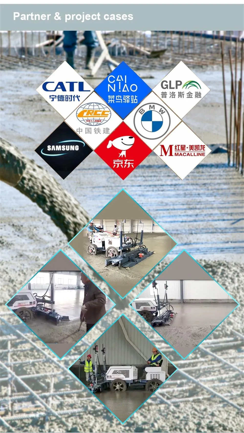
Thanks to All the Friends Who Support and Trust Shandong Vanse Machinery Technology Co., Ltd.
If you want to know more about Shandong Vanse Machinery Technology Co., Ltd. or have any questions, please feel free to contact us:
Our Factory
Shandong Vanse Machinery Technology Co., Ltd.








Share this article

About the Author: Shandong Vanse Machinery Technology Co., Ltd.
Shandong Vanse Machinery Technology Co., Ltd. is a high-tech manufacturer specializing in concrete construction machinery, including laser screeds and related equipment. The company integrates R&D, production, and global sales, with products exported to over 60 countries and widely used in infrastructure projects worldwide.
Previous Post
Next Post
Related Articles
You Might Also Like
How to calibrate the dosage of spreaders to avoid material waste on large-area super flat floors?
Calibrating a concrete topping spreader is a critical step in achieving a high-quality, wear-resistant surface without inflating material costs. On large-area, super-flat commercial floors where strict Floor Flatness (FF) and Floor Levelness (FL) specifications must be met, uneven application of dry shake hardener can compromise the surface density and cause localized variations in the floor profile. Here is a step-by-step professional guide to calibrating the dosage of automatic topping spreaders to ensure precision and eliminate material waste: Before any machine adjustment, establish the exact application rate required by the project specifications. This is typically measured in kilograms per square meter (kg/㎡) or pounds per square foot (lbs/sq ft). Light to medium duty: Usually 3 to 5 kg/㎡. Heavy duty (industrial/logistics): Often requires 5 to 8 kg/㎡ or more. If a heavy application is required, it is usually best practice to calibrate the spreader to apply the material in two separate passes (e.g., 60% on the first pass, 40% on the second) to allow proper moisture absorption from the concrete paste. Automatic topping spreaders, such as those used in tandem with advanced laser leveling or ride-on power trowels, control dosage through two primary variables: Forward Travel Speed: How fast the machine moves across the slab. Dispenser/Auger Speed: How fast the material is pushed through the drop-gate. To avoid waste, these two must be locked in. If the operator slows the machine down but the auger speed remains constant, too much material will be dumped in one area. Ensure the equipment's variable speed controls are set so that the dispensing mechanism is directly proportional to the drive speed. Never perform the initial calibration directly over the fresh concrete. Use the "tarp test" method to dial in the settings: Lay out a pre-measured heavy-duty plastic tarp or catch-tray on a dry, flat surface (e.g., 2 meters by 2 meters). Load the hopper with the specific dry-shake material being used for the project (different materials have different bulk densities and flow characteristics). Set the spreader gate opening and auger speed to the estimated settings. Drive the spreader over the tarp at the exact operational speed that will be used during the pour. Collect and weigh the dispensed material. Divide the weight of the collected material by the square meter area of the tarp. Adjust the gate aperture or auger speed up or down until the exact target weight per square meter is achieved. Moisture in the air or variations in the hardener鈥檚 aggregate size (e.g., metallic vs. mineral aggregates) can change how the material bridges or flows through the hopper grate. Ensure the vibrating screen or agitation shaft inside the hopper is functioning correctly to prevent "rat-holing" (where material forms a tunnel and stops flowing). A smooth, continuous curtain of material is required. If the material clumps, it will drop in piles, requiring aggressive manual finishing that disrupts the FL (levelness) of the slab. Once the large-area pour begins, keep a running tally of the total square meters covered versus the number of bags (or bulk weight) loaded into the hopper. Example: If the target is 5 kg/m虏 and you have covered 1,000 square meters, exactly 5,000 kg of material should have been consumed. Perform this audit early in the pour (e.g., after the first 200 square meters) so minor micro-adjustments can be made to the drop-gate before significant material waste occurs. By dialing in the calibration precisely, operators ensure that the concrete matrix receives the exact surface hardening required for long-term durability, protecting both the project's profit margins and the stringent FF/FL requirements demanded by modern logistics and industrial clients. Note: The parameters provided in this document are for reference only and are not mandatory. Due to differences in technical characteristics between different brands and models of laser levelers, please consult the manufacturer for a suitable solution before actual operation. This reference document assumes no responsibility for any issues arising from failure to follow the manufacturer's instructions.What are the key points to keep in mind when using a concrete laser leveling machine?
The key points to pay attention to when using a concrete laser leveler are crucial, as they directly determine the flatness, quality, and service life of the floor. The following is a detailed summary of the key points to pay attention to in each step, from pre-construction preparation to post-construction maintenance: This phase is the foundation for a smooth construction process. Inadequate preparation will lead to numerous subsequent problems. Base treatment is key: Strength and Density: The base layer (usually crushed stone or stabilized layer) must be compacted to meet the specified bearing capacity requirements (usually ≥1.5 MPa) to prevent cracking caused by base subsidence. Elevation and Flatness: The base layer elevation must be strictly controlled to allow sufficient thickness for the surface concrete. Flatness should not be too poor, otherwise excessive concrete consumption will occur. Cleanliness and Moisture: The base layer surface must be thoroughly cleaned and free of loose dust, oil, and debris. Before pouring concrete, it should be thoroughly moistened with water, but no visible water should be allowed. This is to prevent the base layer from absorbing moisture from the concrete, which could lead to plastic shrinkage and cracking. Precise Formwork Installation: The top elevation of the formwork must align with the designed floor elevation, which is one of the benchmarks for laser leveling. The formwork must be securely supported to prevent displacement or deformation caused by the leveling's movement and concrete compression. The formwork is typically constructed of channel steel, which must possess sufficient rigidity and straightness. Laser transmitter installation and calibration: Location Selection: The transmitter should be mounted in the center or at a high point within the construction area to ensure signal coverage across the entire work surface and avoid signal blind spots. Secure Installation: The transmitter tripod must be securely mounted on solid ground, away from sources of vibration, and monitored during construction to prevent movement. Precise Calibration: The height and level of the laser transmitter must be precisely calibrated according to the design elevation. This is the "brain" of the entire automated leveling system; any error can lead to a complete breakdown. Repeated verification is essential. Equipment Inspection and Debugging: Check the leveling's hydraulic system, engine, scraper, vibrator, and other components for proper operation. Install and inspect the laser receiver, sensor, and control panel to ensure they can properly receive and process laser signals. As the saying goes, "A good cook cannot cook without rice." The quality of the concrete itself is crucial. Mix Design: Commercial concrete should be used, with a strength generally not lower than C25. Slump should be strictly controlled, generally recommended to be between 120mm and 140mm. Excessive slump can lead to segregation, significant shrinkage, and low strength; too little slump can result in poor fluidity and difficulty leveling. Aggregate Selection: The maximum aggregate particle size should be moderate (generally ≤25mm), with good gradation and a standard mud content. Transportation and Placement: The time from unloading to completion of placement should be short to prevent initial setting of the concrete. Segregation should be prevented during transportation. This is the core process and directly demonstrates the advantages of the laser leveling. Concrete pouring and initial paving: Discharge should be even, avoiding concentrated unloading to form large piles to prevent aggregate segregation. Preliminary paving can be performed using small equipment or manually, with the height slightly above the designed elevation (the virtual paving height). Key Points for Laser leveling Operation: Travel Direction: Typically, the paving is performed at a constant speed along the longitudinal direction. Coordination between the scraper and vibrating plate: The scraper is responsible for scraping away excess concrete and providing initial leveling; the vibrating plate uses high-frequency vibration to compact and fine-tune the concrete. The leveling's travel speed must be carefully controlled to ensure sufficient vibration time to achieve a compacting effect, but avoid excessive vibration that may cause concrete segregation. Real-time Adjustment: The operator must closely monitor the data on the control panel. The laser receiver monitors the elevation in real time and automatically adjusts the scraper's height via the hydraulic system, achieving unmanned, automatic leveling. The operator's primary responsibilities are to control movement and monitor equipment status. Critical Process Connection – Gun-Smoothing: After the laser leveling completes an area, but before the concrete begins to set (when a person steps on it and the concrete sinks approximately 3-5mm), gun-smoothing should be performed immediately using a double-disc ride-on trowel. Purpose: Removes minor blade marks left by the laser leveling, smoothes any excess cement slurry, seals surface pores, and prepares for subsequent finishing. This step is crucial to the final surface quality. Laser leveling only completes the "leveling" process. To achieve a high-strength, wear-resistant floor, finishing and maintenance are essential. Finishing (Slurry Calendering): After the concrete has initially set but before final set (when slight footprints remain), use a double or triple trowel with metal discs for rough grinding. Once the surface has further hardened and no visible water is visible, replace the trowel blade and perform a smooth finish. The frequency and timing of smoothing must be carefully controlled. Excessive or premature smoothing can cause surface bleeding and peeling. Smoothing further densifies the surface, improving wear resistance and impermeability. Slotting (Seam Cutting): Timing is critical: The concrete must reach a certain strength (usually 6-10 MPa compressive strength) but still be able to be cut smoothly by the cutter without causing edge cracking. This is generally done within 24-48 hours after pouring (the time varies depending on the temperature). Function: Guides concrete shrinkage cracks to develop in predetermined, uniform locations, avoiding random, irregular cracking. Joint Depth: Typically 1/4-1/3 of the slab thickness. Spacing: Generally determined by the concrete mix ratio and slab thickness, typically 24-36 times the slab thickness. Curing: Curing should begin immediately after the concrete has fully set (after finishing is complete). Recommended Method: Spraying a curing agent or covering with plastic sheeting. The curing agent should be evenly applied to form a dense film; the film should be tightly sealed to prevent evaporation. Time: Curing should last no less than 7 days, with the first 3 days being crucial. Purpose: Provide sufficient moisture for cement hydration to prevent rapid surface water loss, which can lead to cracking and reduced strength. A solid and level base: A weak foundation is destabilizing. Precise laser calibration: This is the system benchmark, and no mistakes can be made. Concrete slump control: Materials are fundamental, and 120-140mm is the optimal range. Timing of leveling and blasting: Mechanized, streamlined operations, seamlessly linked. Timing of finishing and slitting: Rely on experience; applying too early or too late can lead to problems. Timely and adequate curing: The final step that determines ultimate strength and cracking. Strict control of each of these steps can fully leverage the technical advantages of laser levelings to create high-strength, high-flatness, crack-free, high-quality concrete floors. Note: The parameters provided in this document are for reference only and are not mandatory. Due to differences in technical characteristics between different brands and models of laser levelers, please consult the manufacturer for a suitable solution before actual operation. This reference document assumes no responsibility for any issues arising from failure to follow the manufacturer's instructions.Are the transmission parts of concrete power trowels of different brands universal?
– Design differences: When designing trowels of different brands, different transmission methods and structural designs are adopted according to their own technical characteristics, performance requirements and cost control factors. For example, some brands may use belt drive, while others use chain drive or gear drive. The transmission parts used in these different transmission methods are different in shape, size, tooth shape, module, etc., and cannot be replaced with each other. – Specification model differences: Even for the same type of transmission parts, the specifications and models used by trowels of different brands may be different. Taking gears as an example, different brands may choose gears with different modules, numbers of teeth, and pressure angles according to the power, speed, torque and other parameters of the trowel. The sizes and parameters of these gears do not match and cannot be installed on trowels of other brands. – Installation size and interface differences: The transmission parts of trowels of different brands will also be different in installation size and interface design. For example, the connection method between the transmission parts and the engine, working parts, etc., the location and size of the mounting holes, etc., may vary from brand to brand. This means that even if the principles and specifications of the transmission components are similar, they cannot be used interchangeably due to mismatched installation dimensions and interfaces. – Brand-specific technology and compatibility: Some brands may use unique technology or design on transmission components to improve transmission efficiency, reduce noise, enhance durability, etc. These exclusive technologies make the transmission components more compatible and work together with other components of the brand, but also limit their interoperability with other brand components.