Technical Knowledge
Diagnosis and solutions for a normal power trowel machine engine but unable to drive the power trowel disc (such as belt, clutch, etc.)
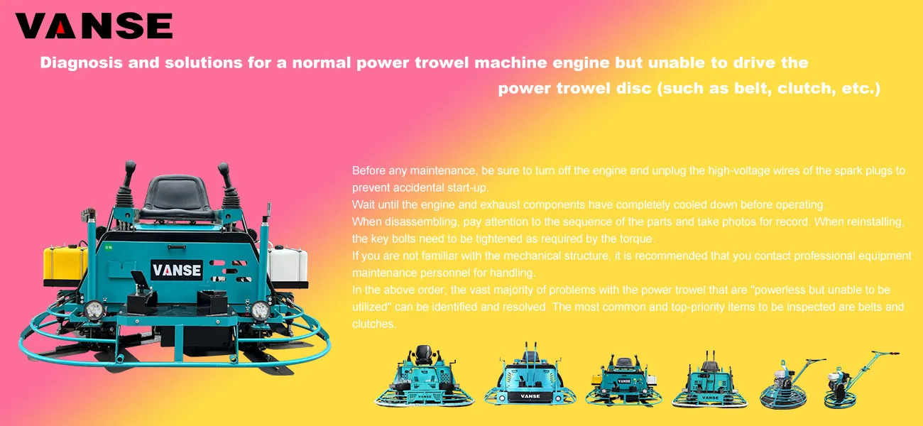
This is a common malfunction of the power trowel machine (also known as the gloss collector or polishing machine). The engine is normal (it can start and the speed sounds normal), but the brake is weak, does not rotate or rotates slowly. The problem must lie in the power transmission system. The following are systematic diagnostic steps and solutions, arranged in order from simple to complex and from outside to inside.
Core diagnostic flowchart
Engine normal → The disc does not move/lacks power → Check the power transmission path
External/Simple inspection → Drive belt system → Clutch system → Gearbox/main shaft
Ⅰ. Quick Self-examination and elimination of External Factors
Before disassembling the machine, rule out the following possibilities first
Excessive load on the power trowel plate: The concrete has passed its optimal finishing time (final setting), and its strength is too high, causing the power trowel plate to be "stuck". Try lifting the machine or testing it on a less hard ground.
The issue with the Angle of the power trowel blade: The installation Angle of the blade is too "flat" (the Angle with the ground is too small), resulting in huge resistance. Adjust the blade to an appropriate Angle (usually 5 to 15 degrees to the ground).
Foreign object jamming: Check whether the area beneath the power trowel plate and around the main shaft are jammed by hard objects such as cement blocks or steel bar heads.
Ⅱ. Key Diagnosis and Resolution: Three Major Systems
System One: Drive Belt (the most common cause)
The polishing machine usually uses a belt to transfer the engine power to the clutch or gearbox.
Symptoms
The engine makes a loud noise when idling, and when wiping the disc, it rotates intermittently or doesn't move at all.
When the machine is working, a burnt smell can be detected (due to the belt slipping and rubbing).
The speed of the power trowel disc is significantly lower than that of the engine, and it is weak.
Diagnostic steps
Shutdown inspection: Turn off the engine and check if the belt is broken, fallen off or severely worn (with cracks on the side and a shiny back).
Tightness check: Press the middle of the belt forcefully with your fingers. The normal deflection should be around 10-15mm. If it is too loose, it will slip; if it is too tight, it will accelerate wear and cause damage to the bearing.
For moderate inspection: Check whether the engine pulley and the driven pulley are on the same plane. Misalignment can cause abnormal wear and detachment of the belt.
Solution
Replace the belt: Be sure to use the original factory or the specified model belt.
Adjust the tightness: Loosen the fixing bolts of the engine base, move the engine position to adjust the tension of the belt, and then retighten the bolts.
Calibration and alignment: Inspect and adjust the installation base of the engine or driven wheel.
System Two: Centrifugal Clutch (Core Fault Point)
Centrifugal clutches are commonly used in power trowels. When the engine reaches a certain speed, the clutch block is thrown out under the action of centrifugal force and combines with the clutch cover to transmit power.
Symptoms
When the engine is running at low speed, the disc does not rotate. At high speed, it may engage but weakly, or it may not engage at all.
When the engine speed changes, there is a "clattering" sound or a metallic friction sound inside, but the power cannot be transmitted out.
Diagnostic steps
Visual inspection (disassembly required) : Remove the clutch protection cover or the wiping plate.
Check the clutch friction block
Wear: Whether the friction plate has worn to its limit (exposed metal or extremely thin thickness).
Oil stains: Whether contaminated by lubricating oil or grease (causing slippage).
Detachment: Whether the friction plate has fallen off from the horseshoe.
Check the clutch spring
Whether the spring is broken, fallen off or fatigued and deformed. Insufficient spring force can cause the clutch block to fail to be flung out or retracted at the correct speed.
Check the inner wall of the clutch cover (drum)
Whether the inner wall is smooth or has deep grooves. Oil stains and grooves can both cause slipping.
Solution
Cleaning: Thoroughly clean all oil stains with carburetor cleaner.
Replacement: Replace the worn clutch friction blocks and broken/deformed springs in a complete set. It is recommended that the friction blocks be replaced in pairs.
Repair/Replacement: If there are deep grooves on the inner wall of the clutch drum, the assembly needs to be repaired or replaced with a lathe.
System Three: Gearbox and Spindle
If both the belt and the clutch are functioning properly, the problem may extend to the final stage.
Symptoms
The engine and clutch work normally, but the main shaft doesn't rotate at all.
When the machine is running, there is an abnormal noise (creaking, clicking) from the gearbox.
The main shaft can be shaken by hand and there is a distinct gap.
Diagnostic steps
Check the gear oil: Whether the gearbox is short of oil or has metal debris (the oil is grayish-white). Lack of oil can cause gears and bearings to burn out.
Check the gears: Open the gearbox to inspect whether the planetary gears or spur gears have broken teeth or severe wear.
Check the bearings: Inspect whether the upper and lower bearings of the main shaft are cracked or stuck. Rotate the main shaft by hand to feel if there is any jamming or abnormal noise.
Check the splines/keyways: Whether the splines of the main shaft connected to the trotter or the keyways of the clutch output are worn flat, which may prevent power transmission.
Solution
Change gear oil: Add gear oil of the specified type and volume.
Replace damaged parts: Replace damaged gears, bearings or splined shafts. This usually requires professional maintenance personnel to carry out.
Summary and troubleshooting sequence table
| Serial number | Inspection site | Possible reasons | Solution | Priority |
| 1 | External and Load | The ground is too hard, the blade Angle is poor, and foreign objects are stuck | Adjust the Angle and clear the foreign objects | High |
| 2 | Drive belt | Fracture, loosening, wear, misalignment | Replace, adjust the tension and correct the alignment | High |
| 3 | Centrifugal clutch | Friction block wear/oil stains, spring breakage | Clean and replace the friction blocks and springs | High |
| 4 | Gearbox | Lack of oil, gear damage, bearing damage | Refuel and replace gears/bearings | In the |
| 5 | Main shaft/spline | The splines are ground flat and the main shaft is bent | Replace the main shaft | Low |
Safety Operation Tips
Before any maintenance, be sure to turn off the engine and unplug the high-voltage wires of the spark plugs to prevent accidental start-up.
Wait until the engine and exhaust components have completely cooled down before operating.
When disassembling, pay attention to the sequence of the parts and take photos for record. When reinstalling, the key bolts need to be tightened as required by the torque.
If you are not familiar with the mechanical structure, it is recommended that you contact professional equipment maintenance personnel for handling.
In the above order, the vast majority of problems with the power trowel that are "powerless but unable to be utilized" can be identified and resolved. The most common and top-priority items to be inspected are belts and clutches.
Note: The parameters provided in this document are for reference only and are not mandatory. Due to differences in technical characteristics between different brands and models of laser levelers, please consult the manufacturer for a suitable solution before actual operation. This reference document assumes no responsibility for any issues arising from failure to follow the manufacturer's instructions.
Thanks to All the Friends Who Support and Trust Shandong Vanse Machinery Technology Co., Ltd.
If you want to know more about Shandong Vanse Machinery Technology Co., Ltd. or have any questions, please feel free to contact us:
Our Factory
Shandong Vanse Machinery Technology Co., Ltd.


Share this article

About the Author: Shandong Vanse Machinery Technology Co., Ltd.
Shandong Vanse Machinery Technology Co., Ltd. is a high-tech manufacturer specializing in concrete construction machinery, including laser screeds and related equipment. The company integrates R&D, production, and global sales, with products exported to over 60 countries and widely used in infrastructure projects worldwide.
Previous Post
Next Post
Related Articles
You Might Also Like
The entire process and key control points of the construction of the diamond sand wear-resistant floor
There are various methods for basement floor construction. Among them, the construction of diamond sand floor and diamond sand floor with curing agent is favored by many real estate projects due to its economic, wear-resistant, pressure-resistant, anti-pollution and easy-to-clean features. However, improper manufacturing processes can also lead to quality issues and potential risks. This article will respectively introduce the diamond sand wear-resistant floor from the perspective of technology and the prevention and control of common problems. 1. Diamond sand floor Compared with ordinary concrete floors, diamond sand floors have better wear resistance, compressive strength and impact resistance, and have a longer service life. However, from the perspective of microstructure, the surface of the diamond sand floor is relatively rough, and the capillary structure of concrete has a low resistance to the penetration, pollution and corrosion of substances such as acids, alkalis and oils. 2. Corundum + cured floor The construction of adding curing agent to the diamond sand floor. When the diamond sand floor is applied with a curing agent, it better makes up for the above deficiencies. Moreover, as the curing agent penetrates and forms a film, it enhances the integrity of the original surface, significantly improving its surface strength and wear resistance. After long-term use, it is obviously superior to the ordinary diamond sand floor in terms of cracking, powdering, and dusting, and is also easier to clean. It has extremely strong wear resistance, pressure resistance and impact resistance The diamond sand floor itself has excellent wear resistance. After adding a curing agent, the strength and hardness of the floor are further enhanced, and its wear resistance, pressure resistance and impact resistance are also significantly improved, and the durability of the floor is greatly enhanced. 2) Prevent sanding and dusting The main advantage of the diamond sand reinforced floor is its ability to prevent sanding and dusting. After the application of the curing agent, the surface hardness (indicated by the diameter of the indentation) and wear resistance (indicated by the length of the grinding pit) can be effectively enhanced. The surface becomes denser and has better integrity, which can effectively prevent sanding and dusting. 3) Waterproof, oil-proof and anti-corrosion The surface of a common diamond sand floor has pores that are hard to see with the naked eye. Water, oil and other corrosive liquids can seep into the interior of the floor through these holes and gaps. The most notable feature of the curing agent is its excellent sealing property, just like coating the floor with a film to prevent erosion. 1. The surface of the floor is firmly combined with the base layer, without any hollowing or sanding phenomena. 2. Surface layer quality: Uniform color, no obvious color difference, no scratches, no slag inclusions. The surface must not have cracks and hollowing is not allowed. 3. Gloss requirements: Achieve medium to high brightness, and the lamp should have a reflective effect when illuminated. 4. Joint: Uniform width, and the inside of the joint should be thoroughly cleaned. 5. The hardness of the floor should reach above 6.5 on the Mohs scale (tested by a hardness tester). 6. The trachoma rate shall not exceed 3 per square meter. 1. The strength of the concrete shall not be lower than C25. 2. The smallest possible water-cement ratio. A water-cement ratio that is too high can cause bleeding on the concrete surface and reduce the compressive strength of the concrete surface. Therefore, the water-cement ratio should be as small as possible, generally controlled below 0.5. 3. Commercial concrete should be used as much as possible. If on-site mixed concrete is used, its slump should be controlled at 1 to 3cm. The slump of commercial concrete is between 12 and 14cm. The diameter of the larger crushed stones shall not exceed 30mm. 4. When the concrete thickness is greater than 8cm, ordinary concrete should be used for pouring; when the concrete thickness is less than 8cm, fine aggregate concrete should be used for pouring. 5. Concrete should be leveled immediately after pouring, with a flatness of no more than 2mm within a 2-meter range. 6. Before the surface layer construction, the base concrete and vibration slurry should be sufficient (not less than 5mm). 7. The mud content of sand and gravel in concrete shall not exceed 2%. 8. After vibration grouting, the bleeding of the concrete should be uniform. If there are water pits, they must be removed and the surface leveled again; otherwise, the flatness of the diamond sand floor construction cannot be guaranteed. 1. Construction of diamond sand floor 1) The ground concrete is poured in sections and leveled immediately after pouring. When multiple locations are being poured simultaneously, pay attention to the construction sequence being carried out in one direction and consider the consistency of the mating surfaces. ② Concrete should be leveled with a long roller or a long straightedge after being pushed flat. Three to five hours after the concrete is poured, it should be observed that there is no bleeding on the surface and it has reached the initial setting state. 2) Use a mechanical trowel to tap the slurry in a round motion. For fine areas, use a wooden trowel to trim the edges. The main purpose is to smooth the concrete surface and reduce the floating slurry. Pay attention to troweling in the same direction as pouring. 3) Sprinkle the wear-resistant aggregate in two batches. In the first batch, evenly spread two-thirds of the wear-resistant material on the already troweled cement floor. 4) For the second time, evenly spread the remaining 1/3 of the wear-resistant material on the surface of the concrete, and use a mechanical trowel with a disc installed to work crisscross and cross at least twice. 5) Use a mechanical trowel (metal disc) to smooth it out multiple times back and forth. For the fine corners and edges, use a manual trowel in coordination with the construction. The time for the next process should be determined based on the temperature and humidity. 6) When the surface of the floor begins to harden, use a mechanical trowel with a metal blade to grind and smooth it, and repeat this operation 3 to 4 times. (Construction workers must wear soft flat shoes to avoid damaging the surface. The fine corners and edges should be polished by hand.) 7) Water curing should be carried out on the polished wear-resistant floor (mainly to prevent the evaporation of surface moisture and ensure the stable growth of the wear-resistant material's strength). The curing period is 7 days. 8) After the surface has cured for a certain period of time (5 to 6 hours after the completion of the wear-resistant material floor), use a mechanical trowel equipped with a metal blade for the final polishing and leveling. 9) Mold and compartment cutting (this can be done according to the actual situation on site and the owner's needs). Mold removal can be carried out the day after the completion of the diamond sand floor. During the operation, be careful not to damage the edge of the floor. The size of the compartments shall be determined by Party A on the third day after the completion of the diamond sand floor. 2. Application of penetrating liquid hardener (commonly known as curing agent) The original color of the diamond sand floor should be cured for more than 14 days, while the colored diamond sand floor usually needs to be cured for 28 days. Only after the color has matured can the penetrating liquid hardener be applied. The specific measures are as follows: Before construction, clean and remove debris, oil stains, paints, curing agents, etc. from the ground. If there are any pits or cracks, they should be repaired in advance with cement-based jointing mortar and maintained for 3 days. If no repair is needed, proceed with the construction directly. 2) Sprinkle water on the base layer until it is fully moistened. Do not sprinkle too much. 3) Use a 50-mesh resin grinding disc to grind the base layer, removing the floating slurry and stains on the base layer to make it free of roughness and gradually smooth. 4) After the 50-mesh grinding is completed, use a 150-mesh resin grinding disc for grinding. After grinding, use a high-power vacuum cleaner to suck up the mud and sewage on the surface of the base layer. 5) Sprinkle water on the surface of the base layer and grind it with a 300-mesh resin grinding disc (the ground should be ground evenly in a grid pattern, and the machine's pushing speed should be one step per second to grind off the remaining materials and fine scratches on the ground). After grinding, grind it with a 500-mesh grinding disc. Then, use a vacuum cleaner to suck up the wastewater and ventilate to dry the base layer. 6) After the base layer is dry, if the surface turns slightly white, apply the concrete sealant and hardener. Sprinkle the material evenly and spread it evenly with a mop. Keep the base layer surface moist for 30 minutes. If there is rapid penetration in some areas and it has dried, sprinkle the material again and use a mop to evenly moisten the base layer. 7) After 30 minutes, the surface of the concrete sealant and hardener begins to thicken. Water should be sprinkled on its surface and pushed back and forth with a long-bristled brush or floor scrubber to dilute the excess hardener and better penetrate into the base layer. After one hour, the excess material and water should be sucked dry with a vacuum cleaner to ensure that the base layer is dry for more than 12 hours. 8) After 12 hours, sprinkle water on the base surface of the completed construction material, and grind it with a 500-mesh resin grinding disc to remove the excess material. Then, grind it with a 1000-mesh grinding process. After grinding, use a vacuum cleaner to suck up the wastewater. 9) After 12 hours, the base layer has basically dried. Then, it is ground and polished with a 2000-mesh resin grinding disc to gradually give its surface a lustrous appearance. 10) For each mesh size, the grinding discs should be cross-ground 3 to 5 times in both the longitudinal and transverse directions. 11) Special treatment ① Corner and edge treatment: Large machinery can only be used for large-scale grinding. For corner and edge positions, a portable Angle grinder should be used for grinding and polishing, following the same method as for large-scale construction. When the base layer has poor strength and severe sanding, it is necessary to reinforce the base layer first, and then proceed with the normal construction process. First, use a 300-mesh resin grinding disc to remove the floating slurry on the surface of the base layer. Then, evenly sprinkle the concrete sealant and hardener to ensure it fully wets and penetrates into the base layer. After 12 hours, when the concrete sealant and hardener has cured and the strength of the base layer has improved, follow the normal process: 50-mesh grinding (water grinding) → 150-mesh grinding (water grinding) → 300-mesh grinding (water grinding) → construction materials → 12-hour drying and curing → 500-mesh grinding (water grinding) → 1000-mesh grinding (water grinding) → 2000-mesh grinding (dry grinding). The aesthetic effect of the floor cannot be achieved without meticulous control during the construction process. Besides strictly adhering to the corresponding techniques and methods, the prevention of common quality problems also requires attention. If the construction is not done properly, many problems will occur during later use. Now let's talk about the common quality problems of the diamond sand wear-resistant floor and how to prevent them. There are mainly three reasons for the color difference of corundum: 1) Material selection issues; 2) The materials were not spread in several portions, the amount of materials used was insufficient, and the thickness was uneven. 3) Maintenance issues: The use of covering with plastic film for maintenance led to uneven evaporation of ground moisture. The area where the film comes into contact with the floor is whitish, while the area where it does not touch the floor is normal in color. Preventive measures Choose a manufacturer with stable and reliable product quality and a good reputation. 2) The spreading of materials should be carried out strictly in accordance with the requirements of the briefing in several portions, with a usage of no less than 5kg/m². 3) Plastic film curing is strictly prohibited. During summer construction, water spraying curing can be adopted in several batches (with an interval of 2 to 3 hours). The allowable deviation of ground flatness is ≤2.5mm/2m in both longitudinal and transverse directions. The reasons for the deviation during construction are: 1) The template setup is out of tolerance; 2) The concrete part was not leveled in accordance with the standard. 3) The wear-resistant material is not evenly spread. Preventive measures 1) Strictly calibrate the elevation lines. Set up steel rods every 2 meters or so. The elevation of the steel rods should be the same as that on the longitudinal seam formwork. Check with a level. 2) The joints should be roughened and leveled in advance. When pouring new concrete, the levelness should be consistent with that of the already poured ground. Any low-lying areas should be replenished and filled in a timely manner. 3) Wear-resistant aggregates should be spread in two portions. The first dosage should be two-thirds of the total dosage. Ensure that the mixture falls evenly. Do not throw it forcefully to avoid the separation of aggregates and cement. After the wear-resistant material has absorbed a certain amount of moisture, it is ground and dispersed with a grinding machine and then combined with the base concrete slurry. For the second spreading, apply the remaining one-third in a direction perpendicular to that of the first spreading. When spreading, first use a straightedge or a straight scraper to measure the levelness, and adjust the uneven areas of the first spreading. After spreading, immediately smooth and polish it, and repeat the grinding machine operation at least twice. When the grinding machine is in operation, it should be carried out alternately in the longitudinal and transverse directions, evenly and orderly, to prevent material accumulation. The third time mainly involves repair treatment. For low-lying areas, materials are replenished and leveled. For corners and edges that cannot be covered by the grinding machine, manual flattening and smoothing are adopted. There are the following situations regarding ground cracks: If the initial setting time of concrete is not well controlled and the diamond sand wear-resistant aggregate is scattered when the moisture content of the concrete is relatively low, it is easy to cause cracks after the construction is completed. 2) Improper construction methods, insufficient thickness of the wear-resistant layer (corundum layer), rapid water loss (such as excessive construction environment atmosphere, etc.), resulting in volume shrinkage and linear shrinkage, causing cracks or hollowing. 3) Improper maintenance: After the completion of construction, the ground was not maintained within the prescribed time or was not adequately watered for maintenance. When the concrete temperature is relatively high, pouring cold water for curing can also cause cracks. Note: When using only the diamond sand floor, it is recommended to use a maintenance agent (oily and film-forming effect) to maintain the floor. If the corundum is reinforced (or epoxy), water curing can be directly adopted. 4) The contraction joint was cut late, and cracks appeared due to thermal expansion and contraction. Under normal circumstances, it is advisable to cut the expansion joints 24 to 48 hours after the completion of the construction of the corundum floor. If it is too late, as the hardness of the floor gradually increases, the floor is prone to "cracking" and developing cracks during the cutting process. 5) If the spacing of the division joints is too large, cracks may also occur. Preventive measures 1) Strictly control the time of the first sprinkling of materials; 2) The concrete layer and the wear-resistant layer (corundum) are constructed simultaneously. 3) The curing time shall be no less than 14 days; 4) Reasonably control the cutting time; The spacing of the division joints should generally not exceed 6m*6m. Cause of formation 1) The roughening and polishing processes are rough. 2) Inadequate maintenance and insufficient maintenance time; 3) The spreading time of wear-resistant aggregates is not well controlled. Preventive measures 1) Use a grinding machine to thoroughly smooth, compact and roughen the ground for no less than three times, and use a floor trowel to thoroughly smooth and level the ground for no less than three times. 2) The curing time shall be no less than 14 days; 3) Strictly control the spreading time of wear-resistant materials. The timing of spreading wear-resistant materials varies as needed, depending on factors such as climate, temperature, and concrete mix ratio. Spreading too early will cause the wear-resistant material to sink into the concrete and lose its effect. If it is spread too late, the concrete will gradually lose its adhesive force due to solidification, preventing the wear-resistant material from fully bonding with it. The most convenient way to determine the time for spreading wear-resistant materials is to let your feet sink about 5mm when stepping on the ground, and then you can start the first spreading work. The moisture at the edges of walls, columns, doors and formwork disappears more quickly. It is advisable to prioritize the application of water to prevent the effect from being reduced due to water loss. 1. Local damage: Clean the damaged area thoroughly, soak it in water to moisten it, then repair it with a putty made of styrene-butadiene latex mixed with water and a hardener material that has screened out the aggregates. Finally, apply the styrene-butadiene latex mixed with water emulsion. 2. Large-scale damage: According to actual needs, lines can be drawn and sawn on the damaged area, the surface layer and part of the base layer can be chiseled off, then the area can be cleaned and moistened, the plain cement slurry can be swept, concrete can be poured, and finally the surface layer of the diamond sand hardener can be applied. 3. Floor peeling: The surface of the wear-resistant diamond sand floor curls and peels. Remedial measures: Cut and chisel off the peeling area (chiseling it into a pitted surface), spray water on the pitted area to moisten it, then apply repair mortar of the same grade as the concrete and press it down to level the ground. Finally, apply a curing agent. 4. Remedial measures for cracks in diamond sand floor: 1) Cracks in areas with requirements for anti-seepage, impact resistance and wear resistance on the surface should undergo surface treatment. 2) For cracks that can affect the integrity, strength, impermeability and steel bar corrosion of the structure, grouting treatment should be carried out. 3) For cracks that endanger the safe operation of buildings, in addition to grouting treatment, other reinforcement measures should also be taken when necessary. 4) Cracks that are sensitive to temperature should be treated when the crack opening is relatively large in the later stage of the low-temperature season. 5) Flexible materials must be used to treat active cracks. Note: The parameters provided in this document are for reference only and are not mandatory. Due to differences in technical characteristics between different brands and models of laser levelers, please consult the manufacturer for a suitable solution before actual operation. This reference document assumes no responsibility for any issues arising from failure to follow the manufacturer's instructions.How do the risks of concrete laser leveling machines and pavers compare in terms of construction safety?
How to compare the risks of concrete laser levelers and pavers in terms of construction safety? In the field of construction, concrete laser levelers and pavers are two important construction equipment, each playing an indispensable role in improving construction efficiency and quality. However, when using these equipment, construction safety is always an important issue that we need to pay attention to. This article will focus on the theme of "How to compare the risks of concrete laser levelers and pavers in terms of construction safety", aiming to provide valuable reference for construction units in selecting and using these equipment by in-depth comparison of the safety risks of the two. First of all, we need to clarify the goal of this article: by comparing the risks of concrete laser levelers and push pavers in construction safety, help construction units better understand the potential safety risks of the two equipment, so as to formulate more effective safety measures to ensure the smooth progress of the construction process and the safety of personnel. In my opinion, the risks of concrete laser levelers and pavers in construction safety have their own uniqueness and commonality. The commonality is that both involve issues such as mechanical operation, electrical safety, and personnel operation specifications; while the uniqueness is reflected in their respective working principles, usage scenarios, and specific safety risks that may be caused. As a high-precision and high-efficiency concrete construction equipment, the safety risks of concrete laser leveling machine are mainly manifested in the following aspects: First, the safety risk of the laser system. The laser leveling machine relies on the laser system to achieve high-precision leveling, but the laser is potentially harmful to human eyes and skin. If the operator does not wear protective glasses or takes improper protective measures, it may cause eye injuries; at the same time, the laser beam may also cause safety risks due to equipment failure or misoperation. The second is the risk of mechanical injury. During the operation of the laser leveling machine, its rotating blades, moving leveling heads and other components may cause mechanical injuries to the operator or nearby personnel. Especially during the start, stop or adjustment of the equipment, if the operation is improper or the personnel are negligent, the risk of mechanical injury will increase significantly. The third is the electrical safety risk. As an electrical equipment, the laser leveling machine has safety hazards such as aging of electrical lines and poor contact. These hidden dangers may cause safety accidents such as equipment short circuit, leakage or fire, causing damage to personnel and equipment. Next, let's look at the safety risks of the paver. As a key equipment for road construction, the safety risks of pavers cannot be ignored: First, pavers need to work closely with transport vehicles during operation, which increases the risk of traffic accidents. If the communication or cooperation between the vehicle driver and the paver operator is not smooth or improper, it may lead to safety accidents such as vehicle collision and personal injury. Second, the hopper, leveling and other parts of the paver are in a high temperature state during operation. If the personnel contact improperly or the protective measures are not in place, burns may occur. At the same time, there are risks such as heat stroke and heat stroke when the paver works in a high temperature environment. In addition, the maintenance of the paver is equally important. If the equipment is not properly maintained or used for a long time without maintenance, it may lead to equipment performance degradation and frequent failures, thereby increasing the safety risk of construction. After comparing the risks of concrete laser leveling machines and pavers in construction safety, we can find that there are certain differences between the two in terms of risk types and manifestations. The risks of laser leveling machines are mainly concentrated in laser systems, mechanical injuries and electrical safety, while the risks of pavers are mainly reflected in traffic coordination, high temperature injuries and equipment maintenance. These differences require us to consider the characteristics of specific equipment when formulating safety measures. In order to reduce these risks, we can take the following measures: first, strengthen the training and education of equipment operators to improve their safety awareness and operating skills; second, formulate strict equipment operating procedures and safety management systems to ensure the correct use and maintenance of equipment; finally, strengthen safety supervision and inspection at the construction site to promptly discover and deal with potential safety hazards. For example, when a construction unit used a concrete laser leveler, it effectively reduced the risk of injury to personnel by the laser system by equipping operators with protective goggles and protective clothing; at the same time, by strengthening equipment maintenance and inspection, it promptly discovered and dealt with problems such as aging of electrical lines, avoiding the occurrence of electrical safety accidents. When using a push-paving machine, the unit effectively reduced the risk of traffic accidents and personal injury by strengthening communication and cooperation with transport vehicles and setting safety warning signs. Through the above analysis, we can see that both concrete laser levelers and push-paving machines have certain risks in construction safety, but the types and manifestations of risks are different. Therefore, when selecting and using these equipment, we need to formulate corresponding safety measures according to the specific situation to ensure the smooth progress of the construction process and the safety of personnel. At the end of the article, I would like to emphasize one point: construction safety is the premise and basis for any construction activities we carry out. Whether using a concrete laser leveler or a paver, we should always be highly vigilant and strengthen safety awareness and the implementation of measures. Only in this way can we ensure the safety and stability of the construction process while improving construction efficiency and quality. In summary, by comparing the risks of concrete laser levelers and push pavers in construction safety, we can more clearly understand the similarities and differences between the two types of equipment in safety risks, which helps us formulate more precise and effective safety measures to ensure the smooth progress of the construction process and the safety of personnel. In future construction, we should also continue to explore and research new safety measures and technical means to further reduce construction safety risks and improve construction safety levels.Establishment and sharing of a troubleshooting manual for common faults of concrete laser leveling
This is a detailed plan on how to establish and share the "Common Fault Troubleshooting Manual for concrete laser leveling". It not only contains the core content framework of the manual, but also provides a full-process approach for establishing, maintaining and sharing this knowledge system. Concrete laser leveling machines are core equipment in modern floor construction, and their operational status directly affects the construction efficiency and floor quality. The establishment of a standardized troubleshooting manual aims to: Enhance efficiency: Quickly locate and resolve faults to minimize downtime. Cost reduction: Avoid major repairs due to minor malfunctions and reduce reliance on senior technicians. Unified standards: Provide a unified troubleshooting process and solutions for both new and experienced operators as well as mechanics to reduce operational errors. Knowledge inheritance: Transform the experience of master craftsmen into replicable and shareable organizational assets. Ensure safety: Standardize operations to prevent safety accidents caused by improper maintenance. (1) Core Content Framework of the manual The manual should adopt a clear, concise and easy-to-query structure. The suggested list is as follows: Cover Equipment name and model Manual version number, formulation/revision date Establish departments/personnel Part One: Safety First General Safety Regulations: All maintenance and inspection work must be carried out after power failure and pressure relief. Personal protective equipment (PPE) requirements: safety helmets, protective glasses, gloves, steel-toed shoes, etc. Safety checklist before operation: such as checking the surrounding environment of the equipment, the effectiveness of the emergency stop button, etc. Part Two: Introduction to Equipment Foundation and Working Principle Diagram of the main components of the entire machine (chassis, scraper, vibrator, laser receiver, hydraulic system, control system, etc.). A brief description of the working principle of the laser elevation control system. A brief description of the principle of hydraulic transmission. Part Three: Quick Troubleshooting Table for Common Faults (Core Part) It is recommended to use a table format, which is clear at a glance. Fault phenomenon Possible reasons Troubleshooting steps Solution Risk Warning/Remarks 1. The leveling accuracy is inaccurate The elevation remains persistently high or low 1. The elevation setting of the laser emitter is incorrect 1. Recheck the elevation of the laser emitter 1. Reset the laser elevation Before calibration, ensure that the ground is stable and the laser signal is unobstructed 2. The initial height of the laser receiver was not calibrated 2. Execute the "centering" calibration procedure for the receiver 2. Re-calibrate the receiver 3. Wear of the machine's reference surface 3. Check the wear condition of the scraper base plate 3. Replace or adjust the scraper base plate The ground shows waves or unevenness 1. The machine's walking speed is unstable 1. Check the walking motor and control system 1. Adjust to a uniform walking speed 2. Pressure fluctuations in the hydraulic system 2. Check the hydraulic oil level, filter element and pump valve 2. Replace the hydraulic oil or filter element and inspect the hydraulic components 3. The ground base is soft and uneven 3. Assess the compaction degree of the base layer 3. Handle the grassroots level 2. Vibration system failure The vibrator is not working or is weak 1. Power supply/circuit failure of the vibrator Check the fuses, circuits and switches 1. Replace the fuse and repair the circuit When repairing the circuit, be sure to cut off the power 2. The vibration motor is damaged 2. Measure the resistance of the motor 2. Replace the vibration motor 3. Blockage or insufficient pressure in the hydraulic oil circuit 3. Detect the hydraulic pressure of the vibration circuit 3. Clean the filter screen and adjust the relief valve 3. Malfunction of the walking system – Walk on one side or not at all 1. The walking track is stuck 1. Clear the debris inside the tracks 1. Clear out debris Do not force the drive to avoid damaging the components 2. Malfunction of the walking motor 2. Check the working pressure of the motor 2. Inspect or replace the motor 3. The control solenoid valve gets stuck 3. Tap or clean the solenoid valve 3. Replace the solenoid valve 4. Hydraulic system failure The system is noisy and the oil temperature is high 1. The hydraulic oil level is too low or the oil quality is incorrect 1. Check the oil level and the type of oil 1. Add or replace standard hydraulic oil Be careful not to get burned when checking the oil level while warming up the machine 2. Air enters the hydraulic pump or it is damaged 2. Exhaust and listen to the sound of the pump running 2. Tighten the oil suction pipe and replace the oil pump 3. The hydraulic oil filter element is clogged 3. Check the filter element clogging indicator 3. Replace the filter element 5. Laser system failure The receiver signal is unstable 1. The laser signal is blocked 1. Check the laser path 1. Clear the obstacles 2. The receiver sensor is dirty 2. Clean the receiver panel 2. Wipe with a soft cloth 3. Environmental disturbances (strong light, vibration) 3. Avoid interference sources 3. Adjust the position of the equipment or add a light shield Part Four: Regular Maintenance and Upkeep Plan Daily maintenance: Cleaning, checking the oil level, and inspecting the fasteners. Weekly/monthly maintenance: Replace the filter element, check the wear of the tracks, and calibrate the laser system. Quarterly/annual maintenance: Replace hydraulic oil and conduct a comprehensive inspection of key components. Part Five: Appendix Key component model table: such as hydraulic oil model, filter element model, fuse specification, etc. Service contact information: Phone numbers of the equipment manufacturer, internal maintenance supervisor, and external service engineer. Fault record sheet: It is used by operators to record the detailed situation of each fault for subsequent optimization of the manual. (2) Manual Compilation Process Establish a project team: Led by the equipment manager, the team members include: senior operators, maintenance technicians, and technical document clerks. Information collection Refer to the official "Operation and Maintenance Manual" for all the equipment. On-site interview: In-depth interviews with experienced operators and maintenance workers, documenting the "classic malfunctions" and "folk tricks" they encountered. Historical data analysis: Analyze previous maintenance record sheets to identify high-frequency fault points. Content writing and visualization The technical document clerk writes the first draft based on the collected information in accordance with the above framework. Use a lot of pictures and ICONS! In the "Possible Causes" and "Solutions" sections, attach physical photos or simple sketches as much as possible, such as "This is the filter element that needs cleaning" or "This is the location of the calibration button". Review and Verification Distribute the first draft to all operators and maintenance workers for trial use and review. Make revisions based on feedback to ensure the content is accurate and the language is easy to understand. Finalization and release: The final version of the manual (V1.0) is formed and enters the sharing process. (1) Sharing form Physical manual Make waterproof, oil-proof and durable loose-leaf manuals and place them in the cab or toolbox of each piece of equipment. Advantages: Readily available on site and does not rely on electronic devices. Disadvantages: Inconvenient to update, prone to damage or loss. Digital Manual PDF electronic version: Distributed to each employee's wechat, email or company shared disk for easy access at any time on mobile phones or computers. Enterprise internal APP/ microsite: Transform the manual content into a simple web page or embed it into the company's OA/ERP system, supporting keyword search for the best user experience. Qr code: Paste a QR code in a prominent position on each device. Scan the code to view the latest version of the electronic manual. This is a highly recommended way! (2) Management and Update Mechanism The manual is not set in stone and a dynamic update mechanism must be established. Designated person in charge: Clearly define the maintenance person in charge of the manual (usually the equipment supervisor). Establish feedback channels: Encourage all users to provide feedback on new faults or better solutions not covered in the manual in the "Fault Record Sheet" or through the wechat work group. Regular review: Every six months or once a year, the project team conducts a centralized review of the manual and updates it based on feedback and technological development. Version control: Each update requires the version number and date to be updated, and everyone should be notified through group announcements, emails, etc., to ensure that everyone is using the latest version. For physical manuals, it is necessary to collect the old versions in a timely manner and replace them with new ones. The value of a manual lies in its use. Formal kick-off meeting: Organize a brief meeting to introduce the purpose, content and access methods of the manual to all employees. Practical training: Use the manual as an essential textbook for new employees' onboarding training and conduct troubleshooting drills in combination with real equipment. Case Sharing Session: Every month, during the safety meeting or morning meeting, an operator is invited to share a case of successfully resolving a fault using the manual, and a small reward is given to stimulate enthusiasm for use. By systematically establishing a detailed and illustrated troubleshooting manual, and adopting a shared approach that combines online and offline methods, supplemented by effective management and training, this "Common Fault Troubleshooting Manual for Concrete Laser leveling Machines" is bound to transform from a mere document into a core asset that enhances team combat effectiveness and ensures equipment availability. Note: The parameters provided in this document are for reference only and are not mandatory. Due to differences in technical characteristics between different brands and models of laser levelers, please consult the manufacturer for a suitable solution before actual operation. This reference document assumes no responsibility for any issues arising from failure to follow the manufacturer's instructions.