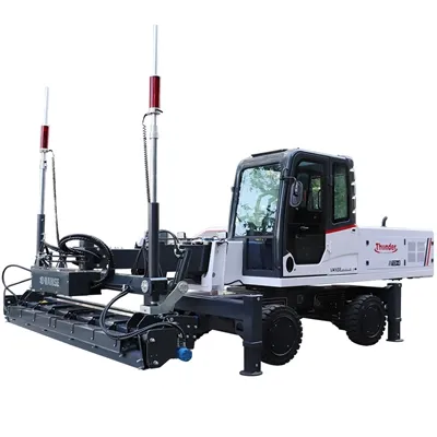
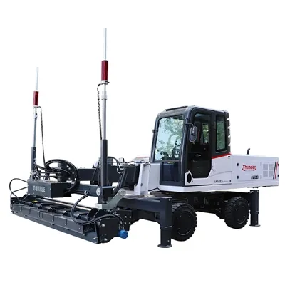
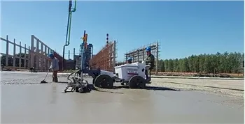
Precision Control Principle of Laser Leveling Machine in Superflat Floor Construction
April 29, 2026
Precision Control Principle of Laser Leveling Machine in Superflat Floor Construction 2
Achieving a Superflat floor (FM1/FM2 or FF 50+) isn't just about having a steady hand; it’s about high-speed physics and real-time data. If you’re a contractor looking to bid on high-spec logistics hubs or robotic warehouses, you need to understand the Precision Control Principle that makes a Concrete Laser Leveling Machine the undisputed king of the job site.
Here is the "under-the-hood" breakdown of how this technology works, and how the Vanse professional fleet turns these principles into flawless results.
1. The "Benchmark": Constant Laser Reference
The heart of the system is the Laser Transmitter. It sends out a 360-degree rotating beam that creates a perfectly horizontal (or sloped) reference plane over the entire work area.
The Vanse Advantage: Most Vanse machines, are designed to work with world-class laser systems (Leica/Trimble). This transmitter stays stationary, ensuring that the "zero point" never shifts, regardless of the terrain or machine movement.
2. The "Eyes": High-Frequency Receivers
Mounted on both sides of the machine's leveling head are the Laser Receivers.
The Principle: These receivers detect the laser beam and send height data to the on-board computer 10 times every second. This is far faster and more accurate than any human eye could ever hope to be.
The Vanse Workflow: Because the Vanse YZ30-4E Telescopic Boomed Laser leveling has such a long reach (6 meters), the receivers can maintain a "clean" signal without the interference of moving wheels on wet concrete, which is a major factor in hitting those ultra-high FL (Levelness) numbers.
3. The "Muscle": Instant Hydraulic Feedback
This is where the magic happens. The computer compares the data from the receivers to the benchmark. If the head is even 1mm too high or low, it sends an immediate command to the Hydraulic System.
The Principle: The hydraulic actuators make micro-adjustments to the leveling head's elevation in real-time. This ensures that the auger (which removes excess concrete) and the vibrator (which consolidates the slab) are always at the exact elevation required. Vanse Integration: To make this process smoother, it helps if the concrete is placed evenly first. Using a Vanse Concrete Distributor or a Mini Dumper to place the mix prevents the laser leveling from "fighting" massive piles of concrete, allowing the hydraulic system to focus on precision rather than heavy lifting.
4. Consolidated Finishing: Preserving the Level
The precision control doesn't stop once the leveling passes. The surface must be finished without losing that laser-perfect flatness.
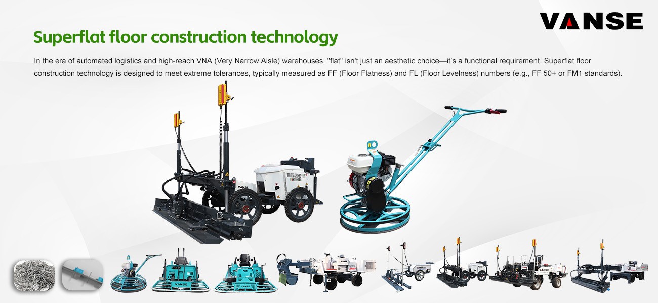
The Principle: You need to densify the slab without creating new "waves." The Vanse Workflow: Use a Vanse Automatic Topping Spreader to apply hardener uniformly. Manual throwing creates "hills" that ruin FF scores. Follow up with a Vanse Ride-on Power Trowel. With its high-torque engine and precision pitch control, it burnishes the floor to a mirror finish while maintaining the flatness established by the laser leveling. Finally, use a Vanse Concrete Cutting Machine (Floor Saw) for crisp contraction joints that won't spall or lift, preserving the floor's long-term FF/FL integrity.
Why "The Vanse System" Wins the FF/FL Game
Foreign buyers and engineers don't just look for a "smoothing tool"; they look for a System of Precision. Here is the ROI for your business:
Control Element
Traditional Manual Result
Vanse Laser Control Result
Reaction Speed
Slow (Human observation)
Instant (10x per second)
Leveling Accuracy
±5-10mm over 3m
±1mm over 3m (Superflat)
Surface Density
Uneven (Manual vibration)
Uniform (High-frequency vibration)
Joint Quality
Ragged (Hand-tooling)
Clean & Straight (Floor Saw)
Labor Cost
High (12+ man crew)
Low (4-6 man crew)
Final Thought
Precision control isn't a "feature"-it’s a requirement. If you are bidding on modern industrial projects, you aren't just competing on price; you are competing on accuracy. By utilizing a complete fleet from Vanse Machinery (www.vansemac.com), you are guaranteeing that every square meter of your floor meets the highest international standards.
Ready to hit those FM1 numbers? Explore the full technical breakdown at Vanse and see how our laser leveling technology can revolutionize your business.
Note:The parameters provided in this document are for reference only and are not mandatory. Due to differences in technical characteristics between different brands and models of laser levelers, please consult the manufacturer for a suitable solution before actual operation. This reference document assumes no responsibility for any issues arising from failure to follow the manufacturer's instructions.
About the Author: Shandong Vanse Machinery Technology Co., Ltd.


Shandong Vanse Machinery Technology Co., Ltd. is a high-tech manufacturer specializing in concrete construction machinery, including laser screeds and related equipment. The company integrates R&D, production, and global sales, with products exported to over 60 countries and widely used in infrastructure projects worldwide.

Whether need buy concrete laser leveling, this article share you
Concrete laser screed machine is based on modern industrial plant, large shopping malls, warehouses and other large areas of cement and concrete ground, such as the ground quality such as strength, flatness, level and other higher and higher demand for development, applied to large-area flooring construction, in the reduction of construction seams at the same time, can also effectively solve the ground air drum, shell, cracking, inequality. About the working principle of the laser leveling machine, it is not complicated to understand, simply is a laser emission laser as the reference plane, through the laser leveling machine laser receiver real-time control of the flathead, so as to achieve high-precision concrete, rapid flattening of the equipmen. Advantage 1: Save on human input. People who have done the grade level know that in a large area of flooring construction, the traditional process of manual construction, the number of team members from about 15 people, a single shift to complete the workload within 700㎡. If using concrete laser screed machine, applied to large area floor ingress construction, the operation effect is greatly improved, 6 workers around the formation of the construction team, the average hour can complete 300m2 paving work, the average single shift can complete 2500 to 3500m2, especially suitable for the duration requirements of tight, large paving area, high quality requirements of the project. Advantage 2: Save capital investment and shorten construction cycle Traditional labor needs to advance the template, waste labor, delay the duration, can not effectively return funds. Concrete laser flatflating machine, high degree of automation, large area block one-time paving construction of the realization, so that the middle of the block does not need a module, in the reduction of branch templates, groove steel at the same time, but also further reduce the construction process, speed up the construction progress. Advantage 3: Very small leveling error The process principle of concrete laser flattening machine is to rely on gasoline generator power generation, electric drive laser measurement and control system, computer control system and servo drive system to complete the flat work by using the flathead, laser leveling machine to find flat does not need to pull the control line, also does not need the side template to control the ground elevation, and by the laser measurement and control system on the flat flating machine real-time control As long as the laser transmitter is not disturbed, no matter where the leveling machine moves, it ensures that the elevation of the ground as a whole after the paving is not affected. Advantage 4: Better overallground on the ground Traditional process construction, one day, one day pouring, can only a piece to jump open construction, the limitations are very large, can not be continuous operation, and the overall nature is not good, easy to cause the cumulative error of construction seams. Concrete laser flatflating machine, applied to flooring construction, it is very easy to achieve a large area of flooring one-time overall paving, this paving technology can be based on the need for arbitrary block construction, continuous operation to the completion of the entire floor, so that the overall nature of the ground is better, which is the use of traditional construction technology can not be done. Advantage 5: The ground is more compact and uniform, reducing the cost of post-maintenance Laser flattener is using 4000 times per minute of high-frequency vibrators, the flat head vibrator yat-bar uniform high-frequency vibration, so that the concrete ground is dense and avoidthes the pressure concentration caused by deformation caused by ground cracking. Can reduce cracks, can effectively solve the ground air drum, shell, cracking, inequality, so that the floor of the late maintenance costs greatly reduced.
Read More
November 26, 2025
Vanse Armor joint
In large-scale concrete floor projects such as industrial plants, logistics and warehousing centers, and large underground garages, joint treatment is the core link that determines the stability and service life of the floor structure. Conventional construction joints, due to their insufficient strength and weak resistance to deformation, are prone to problems such as misalignment, warping, and chipping, which seriously affect the load-bearing performance and functional use of the floor. As a specialized component specifically designed to address such issues, the structural design and application logic of armor joints are of crucial significance for enhancing the quality of floor engineering. Armor joint (also known as armor joint, armored joint, Bama joint, Ba Ma joint, zebra joint) is a composite structural component specially designed for strengthening the joint body of concrete floors. It is usually composed of high-strength metal substrates (such as galvanized steel plates, stainless steel plates, aluminum alloys, etc.), elastic sealing components (EPDM rubber strips, butyl rubber gaskets, etc.) and positioning and fixing systems (shear plates, anchor fasteners, support components). The edge of the seam is a straight metal/composite material cross-section. The upper and lower edges of the seam opening are flush with the ground/wall, without any additional curvature or inclination Angle, and the shape is simple. The edge of the seam is inclined to one side (the slope is usually 3°-5°), or both sides are beveled, forming a groove shape that is "low in the middle and high on both sides". It is advisable to pair it with more metal covers (such as stainless steel and galvanized steel plates). The top adopts an S-shaped curved surface design, formed by stamping steel plates. Combined with the force transmission plate and the telescopic sheath sleeve, it can achieve free expansion and contraction in both longitudinal and transverse directions. Triangular rib design: Triangular reinforcing ribs are welded on the outside of the steel plates of the sub-compartments to enhance the overall rigidity. Thick thrust plate: The thickness of the thrust plate can be selected from 6 to 12mm (material Q355), and it is suitable for heavy-duty areas above 80kN/m². Customized according to the diameter of the column, it is fixed with single-sided support, and the steel plates of the compartments surround the column to form a circular joint. The top edge guard is a flat steel plate, which is cut in the middle along a trapezoidal toothed curve, and the lower part is a punched and bent compartment steel plate and a sawtooth-shaped fixed plate. Cross-shaped, T-shaped, Y-shaped and other combined designs: They are used for the cross-connection of multiple Armor joints. For instance, a cross-shaped node Armor joint can simultaneously connect four straight seams. A stainless steel drainage ditch is integrated at the bottom of the Armor joint, and it is designed in an integrated manner with the steel plate of the compartment. The force transmission plate and the sheath are connected by sliding, allowing the floor to expand and contract freely when the temperature changes. Isolation joint: Also known as "structural separation joint", it is mainly used to achieve physical isolation between the concrete floor and the surrounding building structure. The applicable scenarios are the junctions between the floor and non-floor structures such as walls, reinforced concrete columns, equipment piers and abutments, and embedded part foundations. It separates two structures with different shrinkage coefficients and different load-bearing characteristics through joints, avoiding floor cracking caused by uncoordinated structural deformation. Elastic sealing materials (such as polyurethane sealant) are usually used for filling to ensure the separation effect and water resistance. Cutting joint: Also known as "shrinkage control joint", it is a preset joint body set up to address the problem of irregular cracks that are prone to occur after large-scale concrete pouring. The construction time is after the initial setting of the concrete and before the final setting (usually 24-48 hours after pouring, specifically adjusted according to the strength grade of the concrete). It is cut into shape with a special cutting machine, and the joint depth is usually 1/3 to 1/2 of the floor thickness. The joint spacing is determined according to the strength of the concrete and the ambient temperature (generally 4-6 meters). Its core function is to guide the concrete shrinkage stress to be concentrated and released at the preset joint, avoiding random cracks in the floor. Construction joint/partition joint: A construction joint is a temporary joint set at a preset position due to the excessive area of the floor pouring and the inability to carry out continuous construction at one time, used to divide the pouring sections. The partition joint is a permanent joint body that divides a large area of the floor into fixed-sized partition blocks to control the shrinkage and deformation of the floor in the long term. Essentially, both are "secondary pouring interfaces" of concrete. Such joints, due to the low bonding strength of the concrete joint surface and the uneven distribution of aggregates, have become weak links in the floor structure and are high-risk areas for diseases. Combining the characteristics of concrete structures with the force logic of the floor, the core reasons can be attributed to two points: The construction joint serves as the interface between two concrete pours. Due to the influence of the pouring interval time, the strength development of the concrete poured before and after is not synchronized, and the bonding force at the joint surface is insufficient. When the floor is subjected to vehicle rolling and equipment loads, the blocks on both sides of the joint body are prone to relative displacement, resulting in misalignment (height difference) or warping deformation. After the construction joint is opened, the concrete around the joint is prone to settlement of the internal aggregates under the action of vibration loads (such as vehicle passage and equipment operation), resulting in the separation of mortar and aggregates, and the density and strength of the concrete at the joint decrease. When the load exceeds the load-bearing limit of the joint concrete, edge cracking, corner chipping and other damages are prone to occur, and the damage will gradually expand after it occurs, affecting the structural stability of the entire silo block. Due to the inherent defects of construction joints, in projects with high requirements for the load-bearing capacity and durability of the floor, the use of armored joints has irreplaceable technical value. The metal frame of the armored joint can directly form a rigid connection with the concrete on both sides of the joint body, evenly transmitting the concentrated load at the joint to the surrounding floor, avoiding misalignment and warping caused by concentrated load. Meanwhile, the flexural and compressive properties of the metal substrate can effectively protect the joint concrete and prevent edge chipping caused by aggregate settlement. The elastic sealing components of the armored joint can accommodate the shrinkage deformation of the concrete floor (usually adaptable to ±5mm displacement) and slight settlement of the foundation. This not only prevents the joint from being cracked due to deformation but also ensures sealing performance, preventing oil stains and rainwater from seeping into the foundation. Traditional construction joints need to be repaired on average every 3 to 5 years (such as removing damaged concrete and refitting sealant), and in severe cases, local rework is required. The armored seam, with the anti-corrosion performance of the metal substrate (galvanization, anodizing treatment) and the aging resistance of the sealing components, can have a service life of 15 to 20 years, significantly reducing the frequency and cost of later maintenance. The layout of the armor joints should be determined comprehensively in combination with the floor structure form, load characteristics and usage scenarios. The core should follow the following five technical principles to ensure the effective performance of its functions: Arrange the Armor joints laterally along the load-bearing columns to divide the floor into independent compartments. The size of each compartment must be strictly controlled within 30m×30m. Exceeding this size will cause the shrinkage stress of the concrete to exceed the bearing limit of the armor joint, which is prone to cause cracking in the middle of the silo block. It is strictly prohibited to arrange Armor joints along the direction of directional main channels (such as forklift channels in logistics warehouses and entry and exit lanes in garages) – to prevent vehicle tires from long-term rolling along the seam opening, accelerating the wear of sealing components and deformation of the seam opening. It can be arranged perpendicularly to the direction of the passage to ensure smooth vehicle passage. The length-to-width ratio of floor compartments should be controlled within 1:1.5. If the aspect ratio is too large (such as 1:2 or above), the warehouse blocks are prone to torsional stress due to unidirectional contraction, which may lead to the failure of the Armor joint sealing assembly or the deformation of the metal frame. When armor joints encounter reinforced concrete columns, walls, equipment foundations and other structural bodies, a avoidance distance of 50-100mm should be reserved to prevent the deformation of the structural body and the floor from interfering with each other, which may cause the joint to be squeezed and damaged. Regardless of whether the floor adopts the form of soil foundation bearing or pile foundation bearing, PE sliding film must be laid at the contact surface between the floor and the foundation as well as the contact surface between the floor and the pile cap. PE sliding film can reduce the adhesion between concrete and the base layer, prevent floor cracking caused by foundation settlement, and at the same time provide a stable positioning reference for armor joints, ensuring installation accuracy. In line with the requirements of engineering applications, compared with traditional construction joints and cutting joints, armored joints have the following irreplaceable functional advantages: The metal frame can withstand a uniformly distributed load of 3-5 tons per square meter, making it suitable for high-frequency load scenarios such as heavy-duty forklifts and freight vehicles. The concrete at the joint will not crack due to concentrated loads. It can accommodate ±5mm contraction displacement of concrete floors and ±3mm settlement displacement of the foundation. The elastic sealing components expand and contract synchronously with the deformation, always maintaining the sealed state of the joint. The metal frame forms a "rigid constraint" on the concrete around the joint, preventing aggregate settlement and mortar loss caused by vibration, and fundamentally solving the problems of chipped edges and broken corners. It can be adapted to different types of foundation floors such as soil foundation and pile foundation, and achieve precise fixation in combination with PE sliding film. The installation process is seamlessly connected with the floor pouring procedure, without the need for additional complex processes. The metal substrate undergoes anti-corrosion treatment (galvanizing, anodizing), featuring strong weather resistance and rust resistance. The sealing components are made of anti-aging rubber material, with a service life of over 15 years, significantly reducing the later maintenance cost of the floor. When installing expansion joints, it is essential to meet the requirements of the floor design for levelness and straightness. During the installation process, a level should be used for inspection to ensure that they are precisely vertical in the vertical direction. The force transmission plate should be kept level so that it can slide freely within the plastic sheath when the floor expands and contract freely without generating resistance. In addition, a laser or optical level should also be used for level control and inspection. Step 1 Use nylon thread to position the designed expansion joint. With the assistance of the installation bracket, the straightness and levelness of the Armor joint are adjusted using an optical level until the design value is reached. Step 2 Start installation from the column or wall, and the Armor joint can only be fixed on one side. Use short-threaded steel bars with a diameter of 12 to 14mm to drive into the foundation on one side of the armor joint. Drive two fixed steel bars into each support position, and then weld the armor joint to the fixed steel bars with short steel bars with a diameter of 12mm to 14mm. Step 3 On the first day, pour the unsupported side. The next day, remove the supports and cut off the fixed reinforcing bars above the base layer (to prevent the floor and foundation from being locked and unable to expand or contract freely due to the presence of the fixed reinforcing bars). And pour the concrete on the other side of the armor joint. Step 4 When the curing period of the concrete is over, the edge steel of the armor joint will be gradually and naturally pulled apart. After the contraction stabilizes, remove the garbage in the joint, then fill the elastic adhesive, clean and protect the construction site, and cure for more than 3 days. As a key component for enhancing the quality of concrete floor engineering, the application value of armor joints lies not only in solving the disease problems of traditional joints, but also in improving the long-term stability and load-bearing reliability of the floor structure through standardized structural design and standardized layout principles. For engineering practitioners, it is necessary to strictly follow core principles such as "control of compartment size, reasonable avoidance of passageways, and avoidance of structural structures", and select models in combination with the usage scenarios of the floor and the conditions of the foundation. Only in this way can the technical advantages of the armor joint be fully exerted, and the construction quality and full life cycle value of the floor project be fundamentally improved. Note: The parameters provided in this document are for reference only and are not mandatory. Due to differences in technical characteristics between different brands and models of laser levelers, please consult the manufacturer for a suitable solution before actual operation. This reference document assumes no responsibility for any issues arising from failure to follow the manufacturer's instructions.
Read More
November 17, 2025
Emergency handling and repair procedures for a power trowel after being soaked in water
Soaking a power trowel in water is a serious accident, but proper emergency handling can save the equipment to the greatest extent and prevent secondary damage. Please be sure to follow the following "Golden 24 Hours" emergency handling and repair procedures. Core principles: Power off, drainage, cleaning, and drying. Speed comes first! The most crucial step! Under no circumstances should you attempt to start the engine or connect the power supply (if it is an electric power trowel). Starting with water will directly lead to short circuits in the circuit and motor burnout, causing irreversible damage and extremely high maintenance costs. Engine/electric power trowel: Immediately turn off the ignition switch and remove the key. For the electric model, unplug the battery connection wire (pay attention to insulation). Battery: Disconnect the battery connection wires. First, remove the negative terminal, then the positive terminal. Posture adjustment: Tilt the power trowel to allow as much water inside the gearbox, engine air intake, radiator and other parts to flow out as possible. External cleaning: Use low-pressure clean water to quickly rinse off the mud and dirt on the machine surface to prevent lumps that are difficult to clean after drying. Note: Avoid directly flushing electrical components, bearing seals and other parts with high-pressure water guns. Remove the base/disc of the power trowel: This is the part where sand and mud are most likely to accumulate. Check the air filter: Immediately remove the air filter and check if water has entered. If water gets in, it must be replaced! Under no circumstances should it be used after being dried. Otherwise, sand and dust will enter the engine and cause cylinder pulling. Check the engine oil: Pull out the oil dipstick and check if the oil has turned white (milky white). This is a clear sign that water has entered the engine oil. If water gets in, it must be replaced immediately. Physical drying: Use a clean lint-free cloth or towel to dry all visible moisture, especially around the circuit interfaces, sensors, and spark plugs. Use compressed air (the pressure should not be too high) to dry all hard-to-reach areas such as crevices, circuit joints, engine heat sinks, and gearbox vent holes. You can also use the cold setting of a hair dryer to dry it. Natural ventilation: Place the equipment in a dry and well-ventilated area, open all openable covers (such as the engine hood), and let it air dry naturally. It is strictly prohibited to directly bake with hot air or open flame, as this will damage the circuits and seals. Core principle: Systematic inspection, from the outside in, and handling by modules. Spark plug: Remove the spark plug, check the electrode condition and dry it. You can pull the starter in the air several times to drain any possible accumulated water in the cylinder. Fuel system Fuel tank: Drain all fuel. Even if it seems that no water has entered, condensate water may still be present. Carburetor: Remove the carburetor and perform a thorough cleaning. Water will sink to the bottom of the carburetor, causing it to fail to start or operate unstably. This is a very crucial step. Engine oil: Regardless of the previous inspection results, new engine oil and oil filter must be replaced at this time. Ensure the purity of the oil circuit system. Ignition system and wiring harness: Check all wire joints and high-voltage packs for signs of corrosion or oxidation, and clean and dry them. Gearbox Check the lubricating oil of the gearbox. If water enters (the oil will become cloudy and milky white), it must be completely drained. Clean the interior of the gearbox with diesel or a special cleaning agent to remove moisture and impurities. Refill with brand new gear oil that meets the specifications. Bearings: The grease in the bearings of the main shaft, traveling wheels and other parts will fail if water gets into them. Although it may still be able to rotate in the short term, its lifespan has been severely damaged. It is strongly recommended to remove and replace all the main bearings and add new grease. Clutch and throttle cable: Check for rust or jamming, and add special lubricating oil to maintain its flexibility. Motor: If water has entered the interior of the motor, it must be opened by professional maintenance personnel for cleaning, drying and re-impregnation with insulating varnish; otherwise, it is very likely to burn out. Do not handle it by yourself! Switches and controllers: Carefully inspect all electrical components to ensure they are completely dry and free from corrosion. If you have any doubts, it is recommended to replace it. Cable: Check whether the insulation layer of the cable is damaged. Reassembly: Reinstall all the cleaned, dried and replaced components in sequence. Pre-startup inspection: Reconfirm that the fuel, engine oil and gear oil have been filled in place and all connecting parts have been tightened. Start the engine/motor under no-load conditions and observe whether it runs smoothly and if there are any abnormal noises. Then slowly increase the throttle and check whether the clutch and transmission system are working properly. Finally, conduct a short trial run on the leveled waste mortar or land to check if the smoothing function is normal. If handled promptly and correctly: It may only cost the expenses of replacing the air filter, engine oil, gear oil, spark plugs and cleaning the carburetor (several hundred yuan), and the equipment can return to normal. If not handled properly or delayed, it may lead to serious consequences such as engine cylinder pulling, connecting rod bending, motor burnout, bearing seizing, gear damage, etc. The maintenance cost may be as high as several thousand yuan, and even result in the direct scrapping of the equipment. Finally, it is recommended that if you are not familiar with the internal structure or if the equipment still fails to work properly after following the above steps, please immediately send it to a professional maintenance service station. Explain to the maintenance technician that the equipment has been soaked in water so that they can carry out targeted inspections. Time is money. Correct emergency handling can win precious opportunities for subsequent repairs! Note: The parameters provided in this document are for reference only and are not mandatory. Due to differences in technical characteristics between different brands and models of laser levelers, please consult the manufacturer for a suitable solution before actual operation. This reference document assumes no responsibility for any issues arising from failure to follow the manufacturer's instructions.
Read More
Online now. Replies personally on WhatsAppFionaCustomer specialist
Hi! I am here to help you find the right solution for your project.
You can share your product, capacity, or project needs. Our specialist will help you work out the next step.
Would you like a quick answer? Tap below to speak directly with our specialist on WhatsApp.