Technical Knowledge
What are the common specifications and sizes of concrete power trowels?
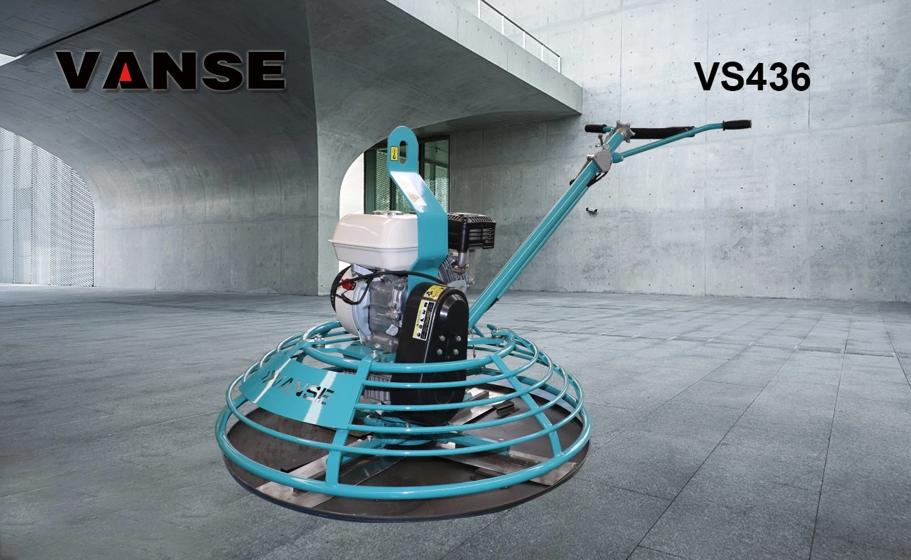
The dimensions of a concrete trowel (also called a concrete screed or concrete leveler) can vary by manufacturer and model, but here are some common ranges:
1. Working width: The working width of a trowel is usually between 60cm and 1.2m. Wider machines are suitable for large areas, while narrower machines are suitable for small or confined areas.
2. Blade diameter: The blade diameter of a trowel is generally between 600mm and 1200mm, which is used to ensure the flatness of the ground.
3. Machine length: The length of a trowel is usually between 1.5m and 2.5m, which affects the machine's operational flexibility and ease of transportation.
4. Machine height: The height of a trowel is usually adjustable, with an adjustment range of approximately 70cm to 110cm to suit different construction needs.
5. Weight: The weight of a trowel can range from 100kg to 300kg, with heavier machines generally providing better compaction.
6. Engine power: The engine power of the trowel can range from 5 horsepower to 20 horsepower or more, depending on the size of the machine and the construction requirements.
7. Fuel tank capacity: The fuel tank capacity is usually between 20 liters and 40 liters, which determines the working time of the machine between refueling.
8. Water tank capacity: For trowels with a water cooling system, the water tank capacity may be between 20 liters and 60 liters.
9. Operating handle length: The length of the operating handle is usually between 1.2 meters and 1.8 meters to provide a comfortable operating experience.
10. Number of blades: Some trowels may be equipped with multiple blades to improve work efficiency.
Please note that these specifications are for reference only, and the specific size should be determined according to the actual construction needs and the model provided by the manufacturer. When choosing a trowel, factors such as the construction environment, construction area, ground type, and required flatness should be considered.
Thanks to All the Friends Who Support and Trust Shandong Vanse Machinery Technology Co., Ltd.
If you want to know more about Shandong Vanse Machinery Technology Co., Ltd. or have any questions, please feel free to contact us:
Our Factory
Shandong Vanse Machinery Technology Co., Ltd.








Share this article

About the Author: Shandong Vanse Machinery Technology Co., Ltd.
Shandong Vanse Machinery Technology Co., Ltd. is a high-tech manufacturer specializing in concrete construction machinery, including laser screeds and related equipment. The company integrates R&D, production, and global sales, with products exported to over 60 countries and widely used in infrastructure projects worldwide.
Previous Post
Next Post
Related Articles
You Might Also Like
Concrete dusting causes and cures
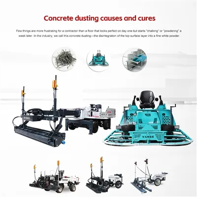
Few things are more frustrating for a contractor than a floor that looks perfect on day one but starts "chalking" or "powdering" a week later. In the industry, we call this concrete dusting-the disintegration of the top surface layer into a fine white powder. If you are dealing with a dusty floor, or better yet, trying to prevent one on your next big warehouse project, here is a professional breakdown of the causes, the cures, and the specialized Vanse equipment that can help you avoid this headache entirely. Most dusting issues happen at the surface level (the top 1-3mm) and are usually tied to how the concrete was moved, leveled, and finished. Too Much Water at the Surface: If the concrete mix is too wet or if you finish the floor while "bleed water" is still present, the water-to-cement ratio at the surface sky-rockets. This creates a weak, porous layer that eventually turns to dust. Poor Distribution and Handling: If the concrete isn't placed uniformly, you get localized wet spots. Over-working the Surface: Trying to "fix" a floor that wasn't leveled properly by over-troweling it can break down the cement bonds before they fully cure. Lack of Surface Hardener: In high-traffic industrial zones, standard concrete isn't enough. Without a wear-resistant topping, the surface will eventually fail. Global buyers know that the best way to handle dusting is to ensure the floor is installed with high-precision machinery. Here is how a Vanse equipment workflow eliminates the risks: To keep your water-to-cement ratio consistent, you need to move the concrete quickly without adding "finishing water." Using a Vanse Concrete Distributor allows for even placement across the slab, while the Vanse Mini Dumper (available in electric or gasoline) allows your crew to transport material to tight spots without the heavy-footprint vibration that causes excess bleed water to rise. The faster you level the floor, the better. A Vanse Concrete Laser Leveling Machine (like the YZ25-4/WS940/WS940C/YZ28-4S or YZ30-4E/YZ40-4E/YZS2/4) uses high-frequency vibration and laser precision to consolidate the slab in a single pass. By getting the floor flat early, you avoid the need to "re-work" the concrete later, which is a major cause of surface weakness. If you want a dust-free floor, a dry-shake hardener is essential. Manual spreading is often uneven, leading to localized dusting. The Vanse Automatic Topping Spreader ensures a perfectly uniform application of wear-resistant materials, "locking" the surface and creating a hard-shell finish that is nearly impossible to scratch. The final "seal" comes from the Power Trowel. A machine like the Vanse VS1046, equipped with a high-torque BRIGGS & STRATTON engine, provides the heavy compaction needed to "burnish" the floor. This process closes the pores of the concrete, making it dense, glossy, and dust-resistant. Dusting often starts at the joints. Using a high-stability Vanse Concrete Cutting Machine (Floor Saw) ensures your contraction joints are straight and clean. Ragged joints from inferior saws can "spall" and break down, creating localized dust and debris in forklift lanes. If the damage is already done, you have three main options: The Chemical Fix: Apply a liquid chemical densifier (usually sodium or lithium silicate). These penetrate the surface, react with the free lime, and turn it into a hard, crystalline structure. The Mechanical Fix: Use a floor grinder to remove the weak top layer, then polish the underlying stronger concrete. The Professional Choice: For severe cases, use a Concrete Cutting Machine to remove the damaged section and re-pour using the Vanse workflow mentioned above. A dusty floor is usually a sign of "exhausted" concrete. By utilizing a complete system from Vanse Machinery (www.vansemac.com)-from the initial Mini Dumper transport to the final Power Trowel pass-you ensure that the concrete's strength stays at the surface where it's needed most. Don't just pour a floor; build a foundation. Visit Vanse today to see our full lineup of Superflat flooring equipment. Note: The parameters provided in this document are for reference only and are not mandatory. Due to differences in technical characteristics between different brands and models of laser levelers, please consult the manufacturer for a suitable solution before actual operation. This reference document assumes no responsibility for any issues arising from failure to follow the manufacturer's instructions.Quality testing method for concrete pavement
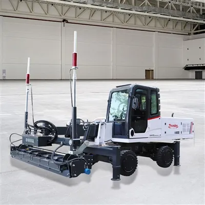
Concrete pavement occupies a vital position in modern transportation infrastructure, and its quality is directly related to the service life, driving safety and comfort of the road. In order to ensure the quality of concrete pavement, comprehensive and scientific quality inspection is indispensable. With the continuous advancement of science and technology, advanced equipment such as concrete laser leveling machine is increasingly widely used in concrete construction, which also puts forward higher requirements for quality inspection methods. The following will introduce the quality inspection method for concrete pavement in detail. As the key cementing material of concrete, the quality of cement has a profound impact on the performance of concrete. When testing cement, the following aspects should be paid attention to: Strength: According to relevant standards, the 3-day and 28-day compressive and flexural strength of cement is measured through cement mortar strength test to ensure that it meets the design requirements. For example, for 42.5-grade ordinary silicate cement commonly used in road engineering, the 28-day compressive strength should not be less than 42.5MPa. Set time: Use a setting time meter to detect the initial and final setting time of cement. Generally speaking, the initial setting time of ordinary Portland cement shall not be earlier than 45 minutes, and the final setting time shall not be later than 10 hours, so as to ensure that the concrete has sufficient operation time during the construction process and can harden in time. Stability: The boiling method is used to test the stability of cement to ensure that the volume change of cement during the hardening process is uniform, without abnormal phenomena such as cracking, so as to avoid quality problems such as cracks in the concrete pavement due to poor cement stability. Aggregates include coarse aggregates (such as crushed stone and pebbles) and fine aggregates (such as natural sand and machine-made sand). The key points of quality inspection are as follows: Particle grading: The particle grading of aggregates is determined by screening tests to ensure that it meets the requirements of relevant standards. Good particle grading can make the aggregates compactly stacked in concrete, reduce the amount of cement used, and improve the strength and durability of concrete. For example, the maximum particle size of coarse aggregates is usually no more than 1/3 of the thickness of the concrete slab, and should meet the requirements of continuous grading. Mud content and mud block content: Excessive mud and mud block content will reduce the bonding force between aggregate and cement paste, affecting the strength and durability of concrete. The mud and mud block content of aggregates are determined by the water washing method. Generally, the mud content of coarse aggregates is required to be no more than 1%, and the mud block content is no more than 0.5%; the mud content of fine aggregates is required to be no more than 3%, and the mud block content is no more than 1%. Robustness: The sodium sulfate solution immersion method is used to test the robustness of aggregates and evaluate their durability under the influence of climate and environmental changes. Aggregates with good robustness can effectively resist the erosion of external factors and extend the service life of concrete pavements. Admixtures can significantly improve the performance of concrete and need to be strictly tested before use: Water reduction rate: The water reduction rate is an important indicator for measuring the performance of water reducers. By comparing the water consumption of concrete mixtures with and without admixtures, the water reduction rate is calculated to ensure that it meets the requirements of the product manual. Generally, the water reduction rate of high-efficiency water reducers should not be less than 15%. Setting time difference: Detect the effect of admixtures on the setting time of concrete. The initial setting time difference and the final setting time difference should meet the construction requirements to avoid abnormal setting time of concrete due to admixtures, which will affect the construction progress and quality. Compressive strength ratio: Determine the compressive strength ratio of concrete with admixtures and benchmark concrete at different ages, evaluate the effect of admixtures on the strength development of concrete, and ensure that admixtures will not reduce the final strength of concrete. The water used for concrete mixing and curing should meet relevant standards and should not contain harmful substances that affect the performance of concrete. The test items include pH value, insoluble matter, soluble matter, chloride, sulfate, etc. For example, it is generally required that the pH value of water used for concrete is not less than 4, and the chloride content (measured in Cl⁻) does not exceed 500mg/L (reinforced concrete) or 1000mg/L (plain concrete). Slump is an important indicator for measuring the fluidity of concrete mixture. At the construction site, a slump cone is used for testing. The concrete mixture is loaded into the slump cone in three layers, and each layer is rammed 25 times. Then the slump cone is lifted vertically to measure the height difference between the cone height and the highest point of the concrete specimen after collapse, which is the slump value. According to the construction requirements, the appropriate slump can ensure the uniformity and density of the concrete during the paving process. For example, when concrete laser leveling machine is used for concrete paving, the slump is generally controlled at 30-50mm to ensure that the concrete can be paved smoothly and can achieve good flatness under the action of the laser leveling machine. For dry and hard concrete mixtures, a Vebe consistency meter is required to detect its Vebe consistency. This indicator reflects the consistency of the concrete mixture under vibration. During the test, the concrete mixture is loaded into the slump cone, and then the slump cone is placed in the container of the Vebe consistency meter. After lifting the slump cone, the vibration table is turned on and the stopwatch is started at the same time. When the concrete surface changes from uneven to flat, the stopwatch is stopped. The recorded time is the Vebe consistency value. The Vebe consistency value should meet the design and construction requirements. Generally, the Vebe consistency of dry hard concrete is between 10-30s. The air content has an important influence on the frost resistance and durability of concrete. The air content of the concrete mixture is tested using an air content meter. The appropriate amount of air content can form tiny bubbles inside the concrete, relieve the stress caused by the freeze-thaw cycle, and improve the frost resistance of the concrete. Generally, the air content of the concrete is required to be controlled between 3% and 5%, and the specific value is determined according to the environment and design requirements of the project. The temperature of the concrete mixture has a significant impact on its performance and construction quality. In a high temperature environment, if the temperature of the concrete mixture is too high, it will accelerate the cement hydration reaction, resulting in too fast slump loss and even false setting; in a low temperature environment, if the temperature of the concrete mixture is too low, it will delay the cement hydration reaction and affect the strength growth of the concrete. Use a thermometer to measure the temperature of the concrete mixture at the mixing site and the pouring site. According to the ambient temperature and construction requirements, take corresponding temperature control measures, such as cooling the raw materials in high temperatures in summer and heating and insulating the concrete in low temperatures in winter. Flatness: The flatness of the base directly affects the thickness uniformity and driving comfort of the concrete pavement. Use a 3m ruler or a flatness meter to detect the flatness of the base surface, and the allowable deviation is generally not more than 10mm. For parts that do not meet the flatness requirements, they should be trimmed to ensure that the base surface is flat, providing a good foundation for the construction of the concrete pavement. Compactness: Insufficient compaction of the base will cause road subsidence and other diseases. The compaction degree of the base layer is tested by sand filling method, water filling method or ring knife method to ensure that it meets the design requirements. For example, for lime-stabilized soil base layer, the compaction degree is generally required to be not less than 95%. Strength: The strength of the base layer is the key to ensuring the bearing capacity of the pavement structure. The strength of the base layer is tested by making specimens for unconfined compressive strength test through on-site core sampling. The strength of the base layer should meet the design requirements to ensure that it can withstand the vehicle load transmitted from the concrete pavement. Casting thickness: During the concrete pouring process, the pouring thickness of the concrete is regularly tested using a steel chisel or other measuring tools to ensure that it meets the design requirements. The thickness deviation of the concrete slab is generally controlled within the range of +10mm, -5mm. Insufficient thickness will affect the bearing capacity and service life of the pavement, while excessive thickness will cause material waste. Vibration quality: Vibration is a key link to ensure the compactness of concrete. The vibration effect can be judged by observing the surface condition of the concrete, such as whether there is slurry overflow and bubble discharge. At the same time, an inserted vibrator can be used to detect the density of the concrete inside to ensure uniform vibration without missing vibration or over-vibration. For concrete pavements constructed with a concrete laser leveling machine, it is necessary to ensure that the concrete has been initially vibrated and compacted before the laser leveling machine is operated to ensure that the laser leveling machine can play a better role and achieve high-precision flatness control. Rebar arrangement (if any): For reinforced concrete pavements, check whether the type, specification, quantity, spacing, position of the steel bars, and the connection method and anchorage length of the steel bars meet the design requirements. Improper steel bar arrangement will affect the structural performance of the concrete pavement, such as bearing capacity and crack resistance. At the construction site, a steel ruler is used to measure the spacing and position of the steel bars, observe the connection and anchorage of the steel bars, and ensure that the quality of the steel bar project meets the standards. 3m ruler method: This is a commonly used road surface flatness detection method. Place a 3m ruler along the longitudinal direction of the road surface and measure the maximum gap between the ruler and the road surface to assess the road surface flatness. Measure 2 locations every 200m, and measure 10 feet continuously at each location. Judge whether the road surface flatness meets the requirements based on the gap value. Generally, the allowable deviation is no more than 5mm. Continuous flatness meter method: This method can continuously measure the road surface flatness, with high detection efficiency and more accurate results. The continuous flatness meter travels along the road surface, collects the elevation data of the road surface through sensors, and calculates the flatness index (such as the International Roughness Index IRI). After the concrete pavement construction is completed, this method can be used to conduct a comprehensive inspection of the road surface to provide detailed data for road surface quality assessment. For roads constructed with concrete laser leveling machines, the continuous flatness meter test results can intuitively reflect the construction effect of the laser leveling machine. The IRI value should generally be controlled within a certain range, such as no more than 2.0m/km, to ensure that the road surface has good driving comfort. Vehicle-mounted bump accumulation meter method: The bumpiness of the road surface is measured by the bumpiness of the vehicle when it is driving on the road. The vertical vibration acceleration of the vehicle is measured by a sensor installed on the vehicle, and the bump accumulation value (VBI) is converted. This method has a fast detection speed and is suitable for rapid detection of large-area road surface flatness. When conducting quality inspection on concrete pavement, the road surface flatness condition can be evaluated according to the VBI value, and verified with other detection methods to fully grasp the road surface quality. Structural depth: The structural depth reflects the macro texture depth of the road surface and has an important impact on the road surface skid resistance. The road surface structural depth is detected by sand spreading method or laser structural depth meter. The sand spreading method is to spread a certain amount of standard sand on the road surface, flatten the sand into a circle with a push plate, measure the coverage area of the sand, and calculate the structural depth value. The laser structural depth meter uses laser scanning technology to quickly measure the road surface structural depth. Generally, the structural depth of cement concrete pavement is required to be between 0.7 and 1.1mm to ensure that the road surface still has sufficient skid resistance under adverse conditions such as moisture. Friction coefficient: The friction coefficient is a direct indicator of the road surface skid resistance. Use a pendulum friction meter or a dynamic friction coefficient tester to detect the road surface friction coefficient. The pendulum friction meter measures the friction force of the pendulum sliding on the road surface when it swings freely from a certain height, and calculates the friction coefficient of the road surface (BPN value). The dynamic friction coefficient tester simulates the friction between the tire and the road surface during vehicle driving and measures the friction coefficient in real time. According to different road grades and usage requirements, the road friction coefficient should reach the corresponding standard value. For example, the BPN value of general urban roads should not be less than 45 to ensure driving safety. Core drilling method: The core drilling method is the most direct and reliable method to detect the strength of concrete pavement. After the concrete pavement is hardened, a core drill is used to drill a core sample on the pavement. The diameter of the core sample is generally not less than 100mm and not less than 3 times the maximum particle size of the aggregate. After the core sample is processed into a standard test piece, a compressive strength test is carried out, and the strength of the concrete pavement is evaluated based on the test results. The core drilling position should be representative, and at least 1 core sample should be drilled every 3km for each lane. The compressive strength of the core sample should meet the design requirements. For example, for a concrete pavement with a design strength grade of C30, the average compressive strength of the core sample should not be less than 30MPa, and the minimum value should not be less than 25.5MPa. Rebound method: The rebound method is a non-destructive detection method. The rebound value of the concrete surface is detected by a rebound hammer. The strength of the concrete is estimated based on the correlation between the rebound value and the concrete strength. When using the rebound method, the measurement areas should be evenly arranged on the pavement. The area of each measurement area should not be greater than 0.04m², and the number of measurement areas should not be less than 10. At the same time, the influence of the carbonization depth of concrete on the rebound value should be considered and necessary corrections should be made. The detection results of the rebound method have certain limitations. It is generally used as an auxiliary detection method of the core drilling method for the preliminary evaluation of the strength of large-area concrete pavements. Ultrasonic rebound comprehensive method: This method combines the advantages of the ultrasonic method and the rebound method. By measuring the ultrasonic sound velocity and rebound value of concrete, the strength of concrete is comprehensively estimated. Ultrasonic sound velocity reflects the density and uniformity of concrete, and the rebound value reflects the hardness of concrete surface. The combination of the two can more accurately evaluate the strength of concrete. The ultrasonic rebound comprehensive method is suitable for batch testing of concrete pavement strength. The accuracy of the test results is relatively high, but the operation is relatively complex and requires professional testing equipment and technicians. Core drilling method: The drilled core sample can not only be used for strength testing, but also can intuitively measure the thickness of the concrete pavement. Use a caliper to measure the thickness of the core sample with an accuracy of 0.1mm. Drill sample cores at 2 locations on the left and right within every 100m of pavement paving width to test the thickness of the board. The pavement thickness deviation should meet the design requirements, and the general allowable deviation is +10mm, -5mm. Radar detection method: Use ground penetrating radar to emit high-frequency electromagnetic waves to the pavement, and detect the thickness of the concrete pavement based on the reflection characteristics of the electromagnetic waves at the interface of different media (such as concrete and base). The radar detection method has the advantages of fast, non-destructive, and continuous detection, and can obtain thickness data of large-area pavements in a short time. However, this method requires professional radar equipment and data analysis software, and the detection results are greatly affected by factors such as the material properties and water content of the pavement structure layer, and calibration and verification are required before use. Appearance inspection: Observe the surface of the concrete pavement with the naked eye to check whether there are cracks. Record the location, direction, length, width and other information of the cracks. For cracks with smaller width, a crack observation instrument can be used to measure and accurately measure the crack width. Generally, cracks with a width of no more than 0.2mm are considered to be small cracks and can be closed on the surface; cracks with a width of more than 0.2mm need to analyze the cause and take corresponding repair measures, such as grouting repair. Non-destructive testing technology: In addition to appearance inspection, non-destructive testing equipment such as ultrasonic flaw detectors and infrared thermal imagers can also be used to detect whether there are cracks inside the concrete pavement. The ultrasonic flaw detector transmits and receives ultrasonic waves, and judges whether there are defects and cracks inside according to the reflection and refraction characteristics of ultrasonic waves when propagating inside the concrete. The infrared thermal imager uses the difference in temperature distribution on the surface of the object to detect internal defects. When there are cracks inside the concrete, a corresponding temperature abnormality area will be formed on the surface, which can be intuitively displayed through infrared thermal images. Non-destructive testing technology can detect hidden cracks inside the pavement, provide a basis for timely prevention and control measures, and ensure the integrity and safety of the pavement structure.What are some common troubleshooting steps for laser system failures?
The laser system of the concrete laser leveling is the core for achieving high-precision screing. Once a malfunction occurs, it will lead to a decrease in the leveling accuracy and affect the construction quality. The following are systematic and common troubleshooting steps. It is recommended to follow the principle of "from simple to complex and from outside to inside". Stop the machine immediately: Turn off the leveling machine and make sure the laser emitter is also turned off to prevent the laser from causing harm to the eyes. Confirm whether the battery power of the laser transmitter and receiver is sufficient. Low battery power can cause unstable signals. Check all cables and plugs for any damage, looseness or poor contact (especially the connection line between the receiver and the main unit of the leveler). Laser receiver: Clean its sensing panel to ensure there is no cement slurry, dust or oil stains covering it. Laser emitter: Clean the emission window to ensure the lens is clean. Mast/Benchmark: Check whether the mast on which the receiver is installed is vertical, stable and free from deformation. Confirm the status of the transmitter Make sure the laser emitter is turned on and in the rotating (sweeping) mode. Check if it is level (observe the bubble level it comes with). Listen to the sound and observe: During normal operation, there should be the sound of the motor rotating, and a moving red dot can be seen on the obstacle when the laser beam appears. Height and position inspection Height: Ensure that the receiver is within the effective working height of the laser plane (usually, the laser plane is best at the middle position of the receiver's sensing rod). If the receiver is too high or too low, no signal will be received. Location: Move the receiver directly near the laser emitter to see if there is a signal. If it is present near but not far away, it might be that the laser plane is blocked or the emitter is not level. Interference screening Check whether there is strong direct sunlight, other laser equipment or strong light source interference in the work area. Try to cover the receiver with a light shield. Equipment replacement test (if conditions permit) : Test with a confirmed normal receiver, or take the faulty receiver to another normally working transmitter for testing. This can quickly determine whether the fault point is the transmitter or the receiver. Inspect the ground and foundation Is the laser emitter tripod set up on a solid and stable ground? The vibration or subsidence of the ground during the pouring process can cause the launcher to shake. Check whether the leveling machine itself shakes violently when moving. Check the mechanical connections Is the connection between the receiver and the mast, as well as the connection between the mast and the body of the leveling machine, firm? Any loosening will cause signal jitter. Check whether the connection hydraulic cylinder/hinge point between the scraper or rammer plate of the leveling machine and the body is too loose, causing free travel. Electrical interference Lay the cables of the laser system separately from the main power line and hydraulic line of the leveling machine to avoid parallel and close contact, so as to reduce electromagnetic interference. Environmental review Is there a large amount of dust and steam in the air? These will scatter laser, causing the signal to weaken and become unstable. High-temperature heat waves can also cause light refraction. Calibration check (the most common cause) : Transmitter calibration: Use the dedicated calibration tool provided randomly and follow the steps in the manual to check and calibrate the horizontal accuracy of the laser transmitter itself. This is the most crucial step. Receiver zero point calibration: At a reference point of known height (such as a pre-set reference post), perform the operation of "zeroing" the receiver or setting the reference height. Reference point and setting check Recheck whether the construction reference point (elevation) is accurate and whether the height set on the transmitter is correct. Confirm whether the mode selected on the control panel of the leveling machine (such as the "Leveling" mode) is correct. Mechanical system linkage inspection After the laser system gives the correct signal, check whether the hydraulic lifting system of the leveling machine responds promptly and accurately. Are there any problems such as clogged hydraulic valves or leakage inside the cylinder? The lifting action can be manually operated to test whether it is smooth and powerful. If none of the above steps can solve the problem, it may involve an internal fault: Transmitter: Internal level sensor failure, motor drive module damage, laser tube aging, etc. Receiver: Damaged sensing element, mainboard failure, etc. Contact the equipment supplier or professional maintenance personnel. Provide detailed fault phenomena and the troubleshooting steps that have been taken. Do not disassemble the core components of the laser emitter or receiver by yourself, especially since the laser emitter has precise optical components and high-precision sensors inside. Non-professional disassembly may lead to permanent damage or calibration failure. Proper storage: After use, clean the equipment thoroughly and store it in a dry, shockproof toolbox. Regular calibration: In accordance with the requirements of the operation manual, conduct official calibration of the laser system on a regular basis (such as every quarter or before the start of each major project). Battery management: Use original or high-quality batteries. Remove the batteries when not in use for a long time. Avoid impact: Handle with care to prevent the laser equipment from being subjected to severe impacts or drops. Observe the fault phenomenon → Power off for safety inspection → Cleaning and appearance inspection → Power supply and wiring inspection → Select the above path for troubleshooting based on the phenomenon (no signal/unstable/poor precision) → Try to replace the component for testing → Contact professional maintenance. Through the above systematic steps, the vast majority of common faults of the laser system of the concrete laser leveling can be solved. Note: The parameters provided in this document are for reference only and are not mandatory. Due to differences in technical characteristics between different brands and models of laser levelers, please consult the manufacturer for a suitable solution before actual operation. This reference document assumes no responsibility for any issues arising from failure to follow the manufacturer's instructions.