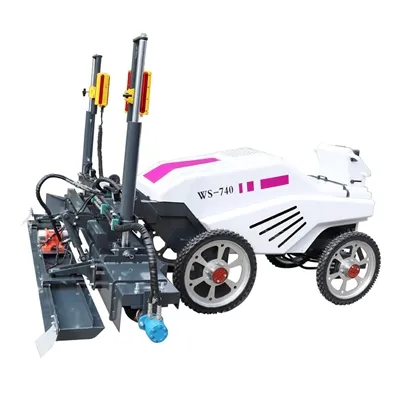
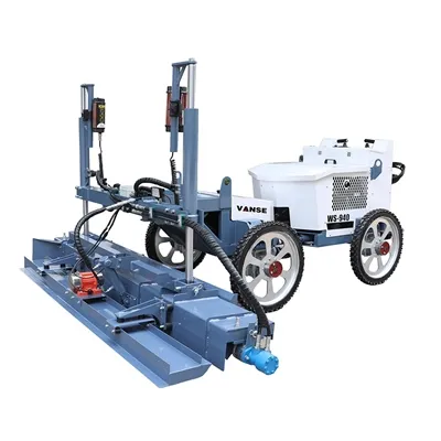
What are the application cases of concrete laser leveling machine in industrial plant construction?
July 15, 2025
What are the application cases of concrete laser leveling machine in industrial plant construction? 14
Concrete laser leveling machines have many application cases in industrial plant construction. The following are some specific project introductions:
✨ Taian Yuluoka new plant floor construction project:Yuluoka Mining Safety Engineering Co., Ltd.'s new plant floor project has a total area of about 18,000 square meters. The project uses large laser leveling machines and spreaders for integrated construction. A 10-centimeter-thick C30 concrete cushion is poured on the base layer, a double-layer 0.15mm PE film is laid, a 6# single-layer bidirectional steel mesh is erected, 20-centimeter-thick C30 concrete is spread and steel fiber is added, and wear-resistant aggregate is spread on the wear-resistant surface layer. The project has a tight schedule. With the stable performance of the laser leveling machine and the cooperation of the construction team, the construction was completed with high quality and recognized by the owner.
What are the application cases of concrete laser leveling machine in industrial plant construction? 15 ✨ Beijing Jeep Automobile Co., Ltd. increased its investment in the production of Mercedes-Benz cars:The main plant floor is a 220 mm thick integrally cast metal wear-resistant steel fiber floor with an area of 44,000 square meters. The owner requires that the surface flatness be checked with a 2-meter ruler and the allowable deviation be 3 mm, which is stricter than the national standard. China Construction First Engineering Bureau used a concrete laser screed machine for paving, and a complete set of ground construction technology with a dowel rod system. The actual construction period was only 33 days, which was 67 days shorter than the planned period for manual paving. All indicators such as ground flatness met the requirements, achieving good social and economic benefits.
What are the application cases of concrete laser leveling machine in industrial plant construction? 16 ✨ Flender Plant Phase III Project:This project is an industrial plant for the assembly and testing of transmission components manufactured by Flender, Germany. The steel fiber concrete metal wear-resistant floor area is 22,000 square meters, the ground thickness is 300 mm, and the ground flatness error is required to be controlled within 3 mm, and the bearing capacity is 15 tons/square meter. The construction party used a concrete laser screed machine for construction, and completed the ground construction in only 25 days, and all indicators met the standards.
What are the application cases of concrete laser leveling machine in industrial plant construction? 17 ✨ Anhui Chuzhou Chahe New Energy Industrial Park Phase II Project:This project was undertaken by China Construction Fifth Engineering Bureau Second Company. The plant mainly produces high-performance N-type TOPCon battery cells. There are AGV intelligent logistics robots running in the field, and the ground flatness requirements are extremely high. The project uses a large concrete laser leveler to construct the concrete floor, ensuring that the flatness deviation of the concrete molding surface is no more than 3 mm, and finally achieving a height difference of less than 1 mm within any 2-meter range. At the same time, the floor is in the form of steel fiber plus steel mesh to reduce the risk of floor sinking and cracking, meeting the factory's requirements for ground flatness and bearing capacity.
What are the application cases of concrete laser leveling machine in industrial plant construction? 18 ✨ New Xi'an Harmony High-Power Locomotive Maintenance Section Project:The industrial plant floor area is 55,000 square meters. The user unit has high requirements for ground flatness, crack resistance and wear resistance, and the surface flatness allowable deviation is 3 mm. The construction unit uses a laser leveler to pave the steel fiber concrete wear-resistant floor construction method. By setting up a force transmission rod system and adding steel fibers, the floor flatness and construction continuity are effectively guaranteed, the construction period is shortened, and the subsequent ground coating requirements are met.
About the Author: Shandong Vanse Machinery Technology Co., Ltd.


Shandong Vanse Machinery Technology Co., Ltd. is a high-tech manufacturer specializing in concrete construction machinery, including laser screeds and related equipment. The company integrates R&D, production, and global sales, with products exported to over 60 countries and widely used in infrastructure projects worldwide.

The influence of the blade configuration of the power trowel machine on the final surface effect of concrete
The configuration of power trowel blades (commonly known as power trowel blades or power trowel discs) directly determines the final flatness, smoothness, strength and wear resistance of the concrete surface. Improper selection and use can lead to various surface defects. The following elaborates in detail on how the configuration of the power trowel machine blades affects the final surface effect of concrete. Shape: Usually wide and thick, with a relatively small number of blades (commonly 3 or 4), and the blades have a large inclination Angle (negative Angle) with the rotating plane. Main functions: Lifting slurry and leveling. Working mode Scraping effect: The larger negative Angle causes the front edge of the blade to "shovel" the concrete surface. It can effectively level the height difference between aggregates (stones), bring the wetter mortar from the lower layer to the surface, and form a "cement slurry layer". Compaction: Through rolling, the surface aggregates are pressed into the interior of the concrete, making the structure more compact. Influence on surface effect: The front side: It provides a relatively smooth base layer rich in cement slurry for subsequent fine plastering. If this step is not taken, direct fine power troweling may bring out the aggregates, resulting in a rough and uneven surface. Negative: If it is used too late (the concrete is too hard), it will loosen the surface, causing cracks or wavy patterns. If used for too long, it will carry out excessive moisture and slurry, resulting in a fragile surface. Shape: Usually thin and narrow, with a large number of blades (commonly 8 to 12), and the Angle between the blades and the rotating plane is small, even close to horizontal (positive Angle or zero Angle). Main functions: Compaction, sealing and polishing. Working mode Patting and smoothing: Numerous and narrow blades pat and smooth the surface of the cement slurry at high speed and frequency to eliminate the marks left by rough smoothing. Sealing the surface: Compact the fine particles in the cement slurry, force the air out, seal the surface capillary pores, and form a dense, pore-free hardened layer. Generating luster: When the concrete is close to final setting, the high-speed rotating precision power trowel rubbing against the surface generates heat, causing the surface of the slurry to "melt" and present a luster. Influence on surface effect: Front: Achieve a dense, smooth, wear-resistant and dust-free surface. The level of glossiness is also determined at this stage. Negative: If used too early, the blade may get stuck in the concrete, creating wavy patterns or even damaging the surface. If used too late, the surface cannot be effectively sealed, which will cause powdering and sanding on the surface. Configuration factors The influence on the surface effect of concrete Applicable scenarios and suggestions Blade Angle This is the most crucial configuration parameter. Rough scraping stage: Use a negative Angle (with the front edge of the blade facing down) to achieve the effect of scraping and lifting the slurry. Fine smoothing stage: Use a small positive Angle or zero Angle (the blade is nearly horizontal) to achieve the effect of patting and smoothing. The larger the Angle, the stronger the cutting force, but the lower the surface finish. The smaller the Angle, the better the polishing effect. Number of blades The more the quantity, the more times each rotation is tapped, and the smoother the smoothing effect will be. Coarse power trowel (3-4 pieces) : Focuses on efficiency and slurry lifting. Fine power trowel (8-12 pieces or more) : Focuses on achieving extremely high flatness and smoothness. The more pieces there are, the finer the final surface will be. Blade material Wear resistance and toughness directly affect lifespan and performance. Spring steel: The most commonly used, it has good toughness, is not easy to break, and offers high cost performance. Tungsten carbide/hard alloy: Extremely wear-resistant, used for treating super-hard concrete or renovating old floors, with an extremely long service life, but expensive. The newness or oldness of the blade Blades that are severely worn cannot function effectively. Old/worn blades: Low efficiency in slurry lifting and polishing can lead to uneven surfaces and poor smoothness. Regular inspection and replacement are necessary. New blade: It can provide the best design Angle and cutting force to ensure the polishing effect. No matter how good the blade is, if it is used wrongly, the opportunity will be wasted. The blade and operation must be switched according to the setting condition of the concrete (the person standing on it should not sink more than 3mm). Phase One: Rough power troweling (Slurry lifting and leveling Timing: After the concrete has initially set, when it sinks by about 5 to 10mm when stepped on. Configuration: Install a coarse power trowel (negative Angle). Operation: The machine runs at a relatively slow speed and mainly focuses on leveling and large-angle scraping. Press the aggregates down and lift the cement slurry up to eliminate the obvious unevenness. Phase Two: Fine Smoothing (Pressing and smoothing) Timing: After the rough plastering is completed, when the concrete further hardens and sinks by about 1-3mm when stepped on. Configuration: Replace with a fine spatula (zero degree or small positive Angle). Operation: The machine speed can be increased and the smoothing can be carried out in a cross direction. At this point, it should be clearly visible that the surface gradually becomes fine and dense, and the rough knife marks are eliminated. Phase Three: Polishing (achieving a bright finish) Timing: When the concrete is close to final setting and there is almost no subsidence when stepped on. Configuration: Continue to use the fine spatula, but you can increase the Angle to a smaller positive Angle (if the blade head is adjustable). Operation: Run at high speed and "drift light" at a small Angle to the ground. The heat generated by friction will slightly liquefy the surface slurry, creating a mirror-like luster. Surface powdering and sanding Reason: The fine power troweling was done too late, and the surface could no longer be effectively compacted and sealed. Or the number of fine power trowel blades is insufficient or the Angle is inappropriate, resulting in poor polishing effect. The surface has wavy patterns and is uneven. Reason: The rough application was done too late, and it was caused by hard scraping and pulling. Or the blade angles are inconsistent (with different degrees of wear); The machine's walking speed is uneven. Exposed aggregates, rough surface The reason is that the coarse coating was skipped or not done thoroughly, and the fine coating was started before a thick enough layer of cement slurry was formed, which brought out the aggregates. Cracks on the surface: Reason: Using a coarse power trowel when the concrete was still too soft (bleeding period) damaged the surface structure. Or the polishing was done too early, causing the blade to sink and the material to be pushed and cracked. The configuration of a power trowel blade is a systematic project that involves using the "right tool" at the "right time" in the "right way". The rough power trowel is the foundation, responsible for creating a smooth and cement-rich working surface. The fine power trowel is the key, responsible for creating a dense, smooth and wear-resistant final surface. The Angle of the blade is the soul, directly determining whether the machine is a "scraper" or a "polishing machine". The timing of construction is the lifeblood. No matter how perfect the configuration is, it cannot play its role if the window period is missed. Only by mastering the relationship among the three proficiently can consistently produce high-quality concrete surfaces. Note: The parameters provided in this document are for reference only and are not mandatory. Due to differences in technical characteristics between different brands and models of laser levelers, please consult the manufacturer for a suitable solution before actual operation. This reference document assumes no responsibility for any issues arising from failure to follow the manufacturer's instructions.
Read More
February 19, 2024
Application of concrete laser leveling machine in special environment
1. Overview The concrete laser leveling is an efficient and high-precision concrete construction equipment that is widely used in concrete construction projects in various ordinary environments. However, in special environments, such as high temperature, low temperature, humidity, corrosion, etc., the application of concrete laser levelinging machines faces more severe challenges. This article will discuss the application of concrete laser leveling machines in special environments, as well as special measures to deal with these environments. 2. High temperature environment In high-temperature environments, concrete laser levelings need to face challenges in equipment heat dissipation and stability. In order to ensure the normal operation of the machine, a series of countermeasures need to be taken. First of all, high-temperature-resistant materials and components should be selected to improve the heat-resistant performance of the equipment. Secondly, the heat dissipation design of the equipment should be strengthened to ensure that the equipment can operate stably in a long-term high-temperature environment. In addition, the equipment should be inspected and maintained regularly to promptly discover and solve various problems that may occur in high temperature environments. 3. Low temperature environment In low-temperature environments, concrete laser levelings need to face challenges in equipment startup and operational stability. In order to ensure the normal operation of the machine, a series of countermeasures need to be taken. First of all, low-temperature-resistant materials and components should be selected to improve the cold-resistant performance of the equipment. Secondly, the thermal insulation design of the equipment should be strengthened to reduce the impact of temperature on the operation of the equipment. In addition, preheating measures should be taken to ensure that the equipment can start and operate smoothly in low temperature environments. At the same time, the equipment should be inspected and maintained regularly to promptly discover and solve various problems that may occur in low-temperature environments. 4. Humid environment In a humid environment, concrete laser levelingers need to face challenges in moisture-proofing and rust-proofing of equipment. In order to ensure the normal operation of the machine, a series of countermeasures need to be taken. First of all, materials and components with moisture-proof and rust-proof functions should be selected to improve the durability of the equipment. Secondly, the sealing design of the equipment should be strengthened to reduce the entry of moisture. In addition, the equipment should be inspected and maintained regularly to promptly discover and solve various problems that may occur in humid environments. At the same time, effective moisture-proof measures should be taken, such as using moisture-proof agents, placing dry explosive agents, etc. to keep the equipment dry and clean. 5. Corrosive environment In corrosive environments, concrete laser levelings need to face challenges in equipment anti-corrosion and corrosion resistance. In order to ensure the normal operation of the machine, a series of countermeasures need to be taken. First, materials and components with anti-corrosion and corrosion resistance should be selected to improve the durability of the equipment. Secondly, the anti-rust treatment of equipment should be strengthened to reduce the impact of corrosion on equipment. In addition, equipment should be inspected and maintained regularly to promptly discover and solve various problems that may arise in corrosive environments. At the same time, effective anti-corrosion measures should be taken, such as using anti-corrosion agents, applying anti-corrosion paint, etc., to extend the service life of the equipment. 6. Summary To sum up, a series of countermeasures need to be taken when the concrete laser leveling machine is used in special environments. For different environmental conditions, appropriate materials and components should be selected, and the design of equipment should be strengthened in terms of heat dissipation, insulation, sealing, and rust prevention. At the same time, effective moisture-proof and anti-corrosion measures should be taken to keep the equipment dry and clean. In addition, the equipment should be inspected and maintained regularly to detect and solve various problems in a timely manner to ensure the normal operation and service life of the machine. When applying concrete laser leveling machines in special environments, special attention should be paid to safety issues and necessary safety measures should be taken to ensure the safety and health of construction workers.
Read More
August 12, 2025
Common faults and solutions of the concrete laser leveling machine
Concrete laser levelers are prone to various malfunctions during long-term, high-intensity operations due to wear, improper operation, or inadequate maintenance. Promptly troubleshooting and resolving faults can prevent extended downtime, reduced construction efficiency, and even equipment damage. The following are common fault types, cause analysis, and solutions: The laser system is the core of leveling accuracy, and its failure directly impacts construction quality. Common problems include: Failure Symptoms: Frequent alarms and flickering indicators on the laser receiver, large deviations in leveling accuracy, and inability to automatically level properly. Common Causes: Laser transmitter battery is low, battery contact is poor, or the transmitter is faulty. Laser receiver lens is contaminated (dust, concrete debris), damaged, or has reduced sensitivity. Environmental interference (such as strong direct sunlight, interference from other nearby laser equipment, or obstacles blocking the signal). Laser transmitter is uncalibrated, resulting in leveling accuracy deviation; or the receiver is loosely mounted or misaligned. Solution: Check the laser transmitter battery level and replace with new batteries. Clean the battery contacts to ensure proper contact. If the transmitter is damaged, repair or replace it. Clean the receiver lens with a soft cloth to remove any stains. If the lens is damaged, replace the receiver lens or the entire assembly. Avoid working in bright sunlight, turn off any interfering equipment, and remove any obstructions (such as rebar or formwork) in the signal path. Recalibrate the laser transmitter's level (using a level). Tighten the receiver mounting bolts until they are properly positioned and secure. Symptom: The laser transmitter does not power on, the receiver indicator light is off, and the device cannot enter automatic leveling mode. Common causes: The laser transmitter power switch is damaged, the battery is exhausted, or the battery compartment is poorly connected. The receiver wiring harness is broken, the plug is loose, or the terminal block is oxidized. The laser module fuse in the control system is blown, or the control board is faulty. Solution: Check the transmitter power switch, replace the batteries, and clean the battery compartment. If the switch is damaged, repair or replace the transmitter. Check the receiver wiring harness for damage, reconnect the plug, and clean the terminals (you can wipe with alcohol). Replace any broken wiring harnesses. Check the corresponding fuse in the control box. If it is blown, replace it with a fuse of the same specification. If the fuse repeatedly blows, check for a short circuit and repair or replace the control board if necessary. The hydraulic system is responsible for driving travel, leveling mechanism lifting and lowering, and vibrating. Failure can lead to reduced equipment performance. Common problems are as follows: Failure symptoms: Slow travel speed, inability to raise or lower the leveling baseplate, and decreased vibration frequency. Common causes: The hydraulic oil tank oil level is too low, the hydraulic oil type is incorrect, or the oil is contaminated (air, moisture, or impurities are mixed in). Severe wear of the hydraulic pump, increasing internal leakage; or the hydraulic pump drive belt is slipping or broken. Clogged hydraulic lines and leaking joints lead to pressure loss; or the overflow valve or pressure reducing valve is faulty, causing pressure regulation failure. Aging or damage to the hydraulic cylinder seals can cause internal or external leakage. Solution: Refill with the same type of hydraulic oil to the standard level. If the oil is contaminated, completely replace the hydraulic oil and filter, and clean the oil tank. Check the tension of the hydraulic pump drive belt and replace any slipping or broken belts. If the hydraulic pump is worn, repair or replace it. Check the hydraulic lines, clear any blockages, and replace seals at leaking joints; calibrate or replace faulty relief and pressure-reducing valves. Disassemble the hydraulic cylinder and replace any aging seals. If the cylinder barrel or piston rod is scratched, repair or replace the cylinder. Symptom: The hydraulic oil temperature exceeds 60°C during operation (some equipment may trigger an alarm), accompanied by jerking movements and increased noise. Common Causes: Radiator surface blockage (dust, concrete debris), reducing heat dissipation efficiency; or cooling fan failure (motor damage, broken belt). Excessive hydraulic system pressure, resulting in prolonged overflow of the relief valve and heat generation; or inappropriate hydraulic oil viscosity (using low-viscosity oil in summer and high-viscosity oil in winter). Improper hydraulic piping layout, excessively long or with numerous bends, increasing fluid resistance; or severe internal leakage in hydraulic components, generating excessive heat. Solution: Use a high-pressure water jet to clean the radiator surface and remove any blockages. Inspect the cooling fan and replace any damaged motor or belt to ensure proper fan operation. Recalibrate the relief valve pressure to the standard value (refer to the equipment manual); replace the hydraulic oil with a viscosity appropriate for the ambient temperature. Inspect the hydraulic lines and replace any excessively bent or aged lines. Repair or replace any components, such as the hydraulic pump and cylinder, that are leaking severely. Symptoms: Oil leakage or dripping from hydraulic line joints; a high-frequency whine emanating from the hydraulic pump or lines. Common Causes: Deterioration or damage of joint seals, or loose, undertightened joints. Vibration and friction leading to damage or cracks in the lines; or loosening of the pipe securing clips, causing the lines to shake and collide. Air mixing with the hydraulic oil causes cavitation, leading to abnormal noise in the pump or lines. Solution: Tighten any loose joints and replace any aged seals (such as O-rings or combination gaskets). If the joint threads are damaged, replace the joint. Repair or replace any damaged lines and re-secure any loose pipe clips to prevent vibration and friction. Check the hydraulic oil tank level and add hydraulic oil to remove air. Loosen the hydraulic pump outlet pipe to vent air, or start the machine and run it at no load to vent air until the abnormal noise disappears. The engine is the power source of the machine. Failure can cause the machine to fail to start or interrupt operation. Common problems include: Failure Symptom: The starter motor operates normally, but the engine fails to start; or it stalls automatically within a few seconds after starting. Common Causes: Insufficient fuel supply: Low fuel tank level, clogged fuel filter, or leaking or clogged fuel lines. Intake System Failure: Severely clogged air filter, resulting in insufficient air intake; or air leak in the intake manifold. Ignition System Problem (Gasoline Engine): Carbon deposits on or damage to the spark plug, or a faulty ignition coil. Diesel Engine: Clogged fuel injectors, insufficient injection pressure, or a preheating system malfunction (in low temperatures). Solution: Add fuel and replace any clogged fuel filters. Check the fuel lines, eliminate leaks, and clear any clogged lines. Clean or replace the air filter element; check the intake manifold for tightness and repair leaks. Clean carbon deposits from the spark plugs and replace damaged spark plugs or ignition coils (for gasoline engines). Clean or replace the fuel injectors and calibrate the injection pressure; check the glow plugs or glow controller and repair the glow system (for diesel engines). Symptoms: Metallic knocking and unusual noises are heard during engine operation; insufficient power is present during operation and cannot meet the load requirements. Common Causes: Low oil level or deteriorating oil quality, resulting in poor lubrication and increased component wear (such as unusual noises on bearings and valve tappets). Poor fuel quality, leading to injector blockage, incomplete combustion, detonation, or black smoke. Insufficient cylinder compression pressure (worn piston rings, poor valve seals), or turbocharger malfunction (for supercharged engines). Cooling system malfunction, engine overheating, resulting in power loss. Solution: Replace the engine oil and oil filter, and refill the oil to the standard level. If components are severely worn, disassemble the engine for repair. Replace high-quality fuel, clean the injectors and fuel lines, and add fuel additives to improve combustion. Check cylinder compression pressure, replace worn piston rings, or repair valve seals; repair or replace the turbocharger. Clean the radiator, check the coolant level, and check the water pump to ensure proper operation of the cooling system. Mechanical structures are directly involved in concrete leveling operations, and failures can easily lead to reduced construction quality. Common problems include the following: Symptoms: Grinding or jerking noises during travel; the machine veers off course, or its speed fluctuates. Common Causes: Worn travel drive chain/gears, insufficient tension, or poor chain lubrication. Uneven wear of travel wheels/tracks, or improper track tension (for tracked equipment). Damaged drive shaft bearings or differential failure (for wheeled equipment). Solution: Adjust chain tension and add grease; replace severely worn chains or gears. Check wheel/track wear and replace worn parts; adjust track tension to standard. Replace damaged drive shaft bearings; repair or replace the differential. Symptoms: Vibrator inoperative or insufficient frequency; scraper deformation or lifting and jamming. Common causes: Vibrator motor failure, hydraulic motor failure, or vibrator shaft jam (concrete debris accumulation). Scraper mounting bolts loose, structural deformation, or lift hydraulic cylinder failure. Worn or insufficiently lubricated pins connecting the leveling mechanism to the machine body, causing lifting and jamming. Solution: Clean concrete debris from the vibrator, repair or replace the motor/hydraulic motor; inspect the vibrator shaft and replace worn parts. Tighten scraper bolts and correct deformation of the scraper; repair or replace the lift hydraulic cylinder. Lubricate the connecting pins and replace severely worn pins and bushings. The electrical system control equipment components work together, and malfunctions can easily lead to operational failures. Common problems are as follows: Symptom: No response when the button is pressed, and the indicator light is off, permanently on, or flashing abnormally. Common Causes: Oxidation or damage to the button contacts, or loose or poor contact in the wiring harness connector. Control panel power failure or damage to control panel components (such as burnt relays or capacitors). Corresponding actuator failure (such as solenoid valves or motors), resulting in abnormal control system feedback. Solution: Clean the button contacts and replace damaged buttons; reconnect the wiring harness connector and tighten the terminals. Check the control panel power supply voltage and replace any burned components. If the control panel is damaged, repair or replace it. Investigate the actuator components and replace the faulty solenoid valve or motor. Fault Symptom: After pressing the emergency stop button, the equipment does not shut down immediately, posing a safety hazard. Common Causes: Internal contacts of the emergency stop button are sticking or damaged, or wiring is loose or disconnected. A faulty relay in the emergency stop circuit prevents power from being cut off. Solution: Replace the damaged emergency stop button and reconnect any loose wiring. Inspect the emergency stop circuit relay and repair or replace the faulty relay to ensure proper circuit disconnection. Simple first, then complex: Prioritize easily observable and accessible areas (such as oil level, connectors, and cleanliness), then delve deeper into internal components. Electrical first, then mechanical: If a malfunction occurs, first check the electrical controls (buttons, wiring harness, sensors), then the mechanical and hydraulic components. Use the equipment manual: Refer to the fault code table in the equipment manual (if available) to quickly locate the source of the fault. Strictly adhere to the daily maintenance schedule and regularly clean, lubricate, and inspect key components to prevent minor issues from becoming major problems. Operators must adhere to standardized procedures to avoid overloading and rough handling, minimizing abnormal equipment wear. A fault log should be established to analyze the causes of frequent faults and optimize maintenance cycles or operating procedures. The above methods can quickly resolve common concrete laser leveling faults, ensuring continuous and stable operation and improving construction efficiency and quality. For complex faults (such as engine overhaul or hydraulic pump replacement), it is recommended to contact professional maintenance personnel or manufacturer technical support. ARMOUR JOINT CONCRETE LASER LEVELING MACHINE POWER TROWEL TOPPING SPREADER