Technical Knowledge
Preventive Measures for Powdering or Surface Peeling Caused by Excessive Troweling
How to Prevent Concrete "Dusting" and "Surface Peeling": Expert Tips for Power Trowel Operators
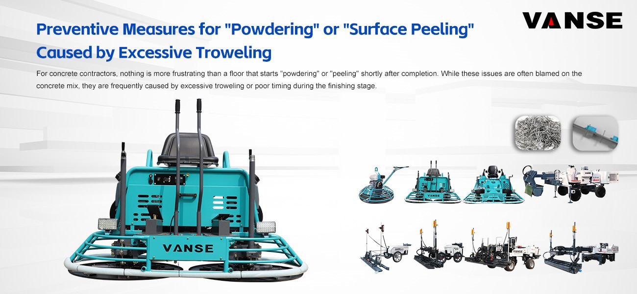
For concrete contractors, nothing is more frustrating than a floor that starts "powdering" or "peeling" shortly after completion. While these issues are often blamed on the concrete mix, they are frequently caused by excessive troweling or poor timing during the finishing stage.
Achieving a durable, wear-resistant surface requires the right technique and, more importantly, high-precision Power Trowel equipment.
1. Master the Timing: Never Trowel Bleed Water
One of the most common causes of surface peeling (delamination) is troweling while bleed water is still present on the surface. Doing so traps water and air under a prematurely sealed top layer, creating a weak bond that eventually peels off.
The Vanse Solution: Professional finishing requires patience. Using a Vanse Ride-on Power Trowel with its responsive control system allows operators to wait for the exact moment when the concrete can support the machine's weight without sinking, ensuring that bleed water has fully evaporated before the final high-speed pass.
2. Precise Blade Pitch Management
"Over-troweling" often happens when the blade angle is too aggressive too early. This "burns" the surface but weakens the structure underneath, leading to a chalky, powdering effect once the floor dries.
Vanse Equipment Advantage: Precision is key. Vanse Power Trowels (such as the VS836H or VS1046H) are equipped with a high-precision blade pitch adjustment system. This allows the operator to make micro-adjustments to the blade angle, ensuring a smooth finish without over-compacting the surface "skin," which is critical for preventing late-stage dusting.
3. Maintain Consistent Speed and Pressure
Uneven pressure from low-quality equipment can cause "shingling" or localized peeling. Look for machines that offer stability and consistent RPM to ensure a uniform finish across large industrial bays.
Vanse Equipment Advantage: The balanced weight distribution and heavy-duty rotor design of Vanse machinery ensure that every square inch of the floor receives equal pressure. The high-torque performance from HONDA GX690 engines provides the steady power needed to maintain constant RPM, reducing the risk of over-working specific areas which typically leads to surface scaling.
4. Avoid Adding Water During Finishing
A common mistake on hot or windy days is "throwing water" on the concrete to make it easier to trowel. This significantly weakens the water-to-cement ratio at the surface, guaranteed to cause powdering.
Pro Tip: Instead of adding water, use a high-efficiency Ride-on Power Trowel from Vanse that can cover the area faster, finishing the job before the surface becomes too unworkable.
Comparison: Why Vanse Equipment Prevents Surface Failures
| Technical Cause of Peeling | Prevention Strategy | Vanse Feature Support |
| Trapped Bleed Water | Delaying the final pass until water disappears. | Smooth, low-speed idling and stable control. |
| Surface Over-working | Reducing blade friction and pass frequency. | Precision Pitch Control for exact finishing. |
| Weak Surface Paste | Avoiding the addition of "finishing water." | High-speed rotation for efficient finishing. |
| Uneven Compaction | Uniform pressure across the entire slab. | Dual-Rotor Balanced Design (VS836/VS1046). |
Summary
Preventing "powdering" and "peeling" is a combination of site discipline and equipment quality. By using Vanse’s range of high-performance Power Trowels ( www.vansemac.com ), you ensure that your operators have the precision tools needed to hit the perfect finish every time, securing a durable, dust-free floor that meets the highest international standards.
Note: The parameters provided in this document are for reference only and are not mandatory. Due to differences in technical characteristics between different brands and models of laser levelers, please consult the manufacturer for a suitable solution before actual operation. This reference document assumes no responsibility for any issues arising from failure to follow the manufacturer's instructions.
Thanks to All the Friends Who Support and Trust Shandong Vanse Machinery Technology Co., Ltd.
If you want to know more about Shandong Vanse Machinery Technology Co., Ltd. or have any questions, please feel free to contact us:
Our Factory
Shandong Vanse Machinery Technology Co., Ltd.








Share this article

About the Author: Shandong Vanse Machinery Technology Co., Ltd.
Shandong Vanse Machinery Technology Co., Ltd. is a high-tech manufacturer specializing in concrete construction machinery, including laser screeds and related equipment. The company integrates R&D, production, and global sales, with products exported to over 60 countries and widely used in infrastructure projects worldwide.
Previous Post
Next Post
Related Articles
You Might Also Like
The application of pervious concrete floor in daily life
The application of pervious concrete floor in daily life As a new kind of ecological friendly pavement material, the color permeable floor has been paid more and more attention especially in the industry. Permeable floor, also known as ecological permeable floor, permeable concrete floor, sand free concrete floor and so on, is the use of coarse aggregate gravel, cementing material, cement and water and other raw materials, after a certain time of mixing evenly, paved into a new type of environmental protection pavement. In the city, the scope of application of this permeable ground is very common, municipal footpath, garden path, city square, upscale residential community outside the garden, parking lot, outdoor sports venues and other outdoor places can be used.The official maintenance guide and recommended cycle for the power trowel machine
The power trowel (concrete power trowel) is a heavy-duty construction equipment, and its performance and service life are highly dependent on regular and correct maintenance. The following is a comprehensive official maintenance guide and recommended cycle, applicable to common fuel (gasoline/diesel) -driven power trowels. Safety first: Before any maintenance, make sure the machine is completely shut down, the engine is off, and the blades/power trowels have completely stopped. Use genuine accessories: Always use the engine oil, lubricating oil, air filter, spark plugs and other accessories recommended by the manufacturer. Record maintenance logs: Detail the date, items and usage hours of each maintenance. Immediately after use: Remove all concrete slurry, dirt and debris from the power trowel, blades, chassis and all parts of the machine. The remaining concrete will harden, causing imbalance and damage to the machine. Clean the body: Wipe the body with a damp cloth to prevent dust from clogging the heat sink and air filter. Check and tighten all bolts and nuts, especially the blade fixing bolts, the power trowel plate connecting parts and the engine base bolts. Vibration can easily cause it to loosen. Check the wear condition to ensure that its edges are flat and free from severe wear or cracks. Change or adjust the Angle as needed. Fuel tank: If the machine will be idle for more than 30 days, it is recommended to empty the fuel in the fuel tank and carburetor, or add fuel stabilizer to prevent clogging of the fuel lines and carburetor. Air filter In environments with extremely high levels of dust (such as concrete construction), it may be necessary to clean after each use. Remove the paper filter element and gently tap it to remove the dust. If there is compressed air, blow it clean from the inside out (the air pressure should not be too high). Check if the filter element is damaged. If it is, it must be replaced. Check and clean the sponge pre-filter element (if any). On a level ground, check the engine oil level with an oil dipstick. Add engine oil of the specified grade (SAE 10W-30 or as per the instructions) as needed. Check the lubricating oil level of the gearbox (if there is an observation window or dipstick), and add the specified gear oil if necessary. Change the engine oil (for four-stroke engines) : The first change should be made 25 hours after the first use, and then every 50 hours thereafter. When warming up the machine, drain the old oil and add new engine oil to the specified amount. Thoroughly clean the air filter and consider replacing it: Even if cleaned frequently, the paper filter element has a lifespan and should be replaced regularly. Check/clean the spark plugs: Remove carbon deposits, check the electrode gap, and adjust it to the value specified in the manual (usually 0.6-0.8mm). Use a grease gun to apply high-quality lithium-based grease to all oiling nozzles (steering bearings, lifting screws, connecting rods, etc.). Check the movable joint areas and apply lubricating oil manually to prevent rust. Inspect the drive belt/V-belt: Check for cracks, wear or looseness, and adjust the tension as required by the manual or replace it. Replace the air filter element: Regardless of its appearance, it is recommended to replace it regularly. Replace the fuel filter: Clean the fuel system and replace the fuel filter screen or filter. Check/adjust idle speed and throttle line: Ensure stable engine idle speed and flexible operation. Thoroughly inspect the gearbox oil: If there is turbidity or metal shavings, consider replacing the gear oil. Comprehensive major maintenance: It is recommended to send it to an authorized service center for handling. Deep cleaning: Thoroughly clean the entire machine. Replace all filters: air, fuel and oil filters (if any). Replace spark plugs: Replace with new spark plugs of the specified model. Inspect/Replace carbon brushes (for motorized power trowels) : For electric power trowels, check the wear of the motor carbon brushes and replace them in a timely manner. Fuel system completely drained Drain all the fuel from the fuel tank and carburetor. Or fill up the tank with fuel and add fuel stabilizer, and run the engine for a few minutes to allow the stabilizer to circulate to the carburetor. Battery maintenance (electric start model) Disconnect the negative terminal of the battery. Charge the battery and maintain it regularly (charge it once every 1-2 months). Storage location: Store the machine in a clean, dry and well-ventilated room and cover it with a cover. If the equipment is idle for more than one month during the non-construction season, the following steps must be carried out Fuel treatment: As mentioned above, drain or add stabilizer. Engine protection Inject a small amount of engine oil into the spark plug hole, pull the starting rope several times to lubricate the cylinder with the engine oil, and then install the spark plug. Place the engine at the top dead center of compression (stop when you feel resistance when pulling the start rope). Rust prevention treatment: Apply rust prevention oil to all exposed metal parts. Lift the power trowel: Use a wooden board to prop up the power trowel and lift it off the ground to reduce the pressure on the tires and suspension. Oil and water inspection: Engine oil, fuel oil. Visual inspection: Check for any oil leakage or damaged components. Operation test: Start the machine under no-load conditions in a safe area to check if the steering and lifting are flexible and if there are any abnormal noises. Protective devices: Ensure that all protective covers (belts, gears) are in good condition and firmly installed. Final reminder: This guide is general advice. For the most accurate maintenance requirements, please be sure to refer to the "User Operation and Maintenance Manual" of the polishing model you have purchased. Adhering to the cycles and norms specified in the official manual for maintenance is the key to ensuring the performance, safety and service life of the equipment. Note: The parameters provided in this document are for reference only and are not mandatory. Due to differences in technical characteristics between different brands and models of laser levelers, please consult the manufacturer for a suitable solution before actual operation. This reference document assumes no responsibility for any issues arising from failure to follow the manufacturer's instructions.What are the advantages of using laser leveling machines in building floor construction?
The construction industry of building floor is developing rapidly at present, and the use of construction machinery such as laser leveling machine is becoming more and more frequent. So, why do we have to recommend this equipment to everyone among many engineering machinery? In fact, there are certain reasons. Next, let's take a look at the introduction of the following article! The traditional process has a large number of construction workers, and requires templates (channel steel), dotting, and paving. It requires about 20 people. The construction area is 700 square meters per day. The total number of people using concrete laser leveling machine is more than half of that of traditional processes. It can be operated by one person. The construction area is 2500 square meters-3500 square meters per day, which greatly reduces labor costs. The traditional process leveling requires templates to control the elevation of the ground and pull the control line. The elevation error is large. The levelness and flatness of the entire floor cannot be guaranteed. The laser point transmitter is used, which is suitable for one-time paving of large areas. There is a laser measurement and control system to control the elevation in real time. There is no need to pull the wire for leveling, and there is no need to support the side plate in the middle to control the ground elevation. This avoids the elevation error caused by the vibration of the template (channel steel) during the construction process, and also reduces the elevation error caused by traditional manual block support. Traditional construction technology, one day of formwork, one day of pouring, can only be skipped one by one, which has great limitations, cannot be operated continuously, and has poor integrity, which is easy to cause cumulative errors in construction joints. The laser leveling machine has higher efficiency and integrity for one-time overall paving of large areas of floor. The completion of the entire floor makes the ground integrity better, which is completely impossible for traditional construction. The high-frequency vibrator of 4000 times per minute allows the leveling head vibrator to produce uniform high-frequency vibration, making the concrete floor denser and more uniform. As a leader in concrete laser leveling machines, the laser leveling machines produced by our company can achieve large-area construction. By solving the concrete surface layer in one go, all "common quality problems" caused by secondary practices are completely eliminated. We will continue to provide customers with reliable products and more complete services.