Technical Knowledge
How to evaluate the application prospects of concrete laser leveling machine in the construction industry?

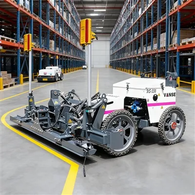
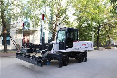
Concrete laser screed has broad application prospects in the construction industry. With the continuous improvement of the construction industry's requirements for construction quality and efficiency, and the continuous investment in infrastructure construction, its market demand is expected to grow further. The specific analysis is as follows:
⛴️ Significant technical advantages:
The concrete laser screed adopts advanced laser technology, which can accurately control the leveling accuracy, can monitor and adjust in real time, ensure that the concrete surface is uniform and smooth, and can effectively solve the problems of hollowing, peeling, cracking, and inequality on the ground. It is particularly suitable for projects such as industrial floors and warehouse facilities that require high ground flatness. In addition, it has a high degree of automation and can be operated by a skilled technician. Compared with traditional manual leveling, it greatly improves work efficiency and reduces labor costs.
⛴️ Adapt to a variety of construction scenarios:
The concrete laser screed has strong versatility. Whether it is a small residential project or a large commercial development project, it can be adjusted according to the specific requirements of the work. It can handle different types of concrete and adapt to various structural designs. It can be used in industrial plants, large shopping malls, airport runways, highways and other places.
⛴️ In line with environmental development trends:
As sustainable development becomes an increasingly important consideration in the construction industry, concrete laser leveling machines help reduce the overall impact of construction projects on the environment by reducing the need for physical labor and waste of rework materials, meet the requirements of green building development, and are more likely to be recognized by the market.
⛴️ Technological innovation drives development:
With the continuous advancement of science and technology, concrete laser leveling machines are also constantly innovating and upgrading. For example, the automatic leveling device for outriggers developed by Shandong Wanshi Machinery Technology Co., Ltd. can monitor the changes in ground height and adjust the position of outriggers in real time through high-precision sensors and intelligent control systems, further improving the accuracy and efficiency of construction. In the future, the integration of more advanced technologies will continuously improve its performance and make its application more extensive.
⛴️ Continued growth in market demand:
The country's investment in infrastructure construction continues to increase, and the number of various construction projects has increased, and the demand for concrete leveling construction has also increased accordingly. At the same time, modern buildings have higher and higher requirements for ground quality, which is difficult to meet with traditional leveling methods. As a more advanced construction equipment, concrete laser leveling machines will usher in more market opportunities.
However, concrete laser leveling machines also have limitations such as high equipment cost, high technical requirements for operators, and laser signals that are easily interfered with in complex environments. However, with the development of the industry and the maturity of technology, these problems are expected to be gradually improved, and its application prospects remain very broad.

Click the below to jump immediately!!!

ARMOUR JOINT

CONCRETE LEVELING MACHINE


POWER TROWEL

SLIPFORM MACHINE


TOPPING SPREADER

Thanks to All the Friends Who Support and Trust Shandong Vanse Machinery Technology Co., Ltd.
If you want to know more about Shandong Vanse Machinery Technology Co., Ltd. or have any questions, please feel free to contact us:
Our Factory
Shandong Vanse Machinery Technology Co., Ltd.








Share this article

About the Author: Shandong Vanse Machinery Technology Co., Ltd.
Shandong Vanse Machinery Technology Co., Ltd. is a high-tech manufacturer specializing in concrete construction machinery, including laser screeds and related equipment. The company integrates R&D, production, and global sales, with products exported to over 60 countries and widely used in infrastructure projects worldwide.
Previous Post
Next Post
Related Articles
You Might Also Like
Teach you a small roller machine maintenance car paint tips
The surface of a small roller often rusts, and we may say that it is the consequence of the surface paint being cut. In fact, in addition to the common collision, scratches, the car when the tires hit the small stones hit the paint, but also make the paint a peeling off a small point, a long time will produce small rust. And these small scars because most of the inconspicuous, easy to be ignored. Small road transport on the way, encountered rain and snow or passing muddy water pavement is inevitable, the bottom of the car and some other space and the car floor, etc. are easy to accumulate sludge, if not timely cleaning, which will make moisture To hide. To always check, and to keep the door and the body parts of the drainage holes open, check the car cover the humidity, to prevent the rusty parts of the floor. There are some small paint a small road roller, high-speed running in the process of sand particles hit the body may also cause small scratches. For this type of car, you can seal the body glaze, it can form a solid mesh protective film to improve the hardness of the paint, the effect can be maintained for about a year. In addition, for the bottom of the vehicle can be chassis armor or plastic, so you can protect the chassis acid rain, anti-corrosion, so that the original protective layer is not easy to dry, off, but also to prevent the impact of small stones on the chassis. For the small roller body has appeared some minor scratches or rust, if you are placed regardless of easy to rust, but not worth the money to the beauty shop. You can do it yourself with some easy way to handle it. Here to teach you a simple and effective way: found a new small scars, the toothpaste gently wipe the circle painted on the scratch. This can generally reduce the mark imprint, you can simply play a role in isolation, to prevent rust, no problem in the short term. The above is Xiangjiang Xiao Bian for your finishing on the surface of the maintenance of the road, you learn it?How to Control the Quality of Ultra-Large Laser-Leveled Wear-Resistant Concrete Floors
Quality control for ultra-large laser-leveled, wear-resistant concrete floors requires a comprehensive process encompassing "pre-construction prevention, in-construction control, and post-construction acceptance." Combining the technical characteristics (laser precision leveling and the synergistic effect of wear-resistant materials) with the challenges of ultra-large-scale construction (temperature cracking, flatness control, and interface bonding), a control system is established across five core dimensions: personnel, materials, equipment, process, and environment. This can be broken down into the following key steps: Pre-construction preparation for ultra-large flooring directly impacts subsequent quality stability, focusing on addressing three key issues: "unified technical standards, adequate resource allocation, and proactive risk mitigation." Drawing Refinement and Technical Briefing: Based on the building's function (e.g., load and flatness requirements for factories and logistics warehouses must be clearly defined), floor compartment design should be refined (extra-large areas should be divided into 6m×6m or 8m×8m compartments to avoid thermal stress cracking). Key parameters should be clarified, including laser leveling accuracy (typically ±3mm/2m), wear-resistant material dosage (approximately 5-7kg/m2 for metallic aggregates, 3-5kg/m2 for non-metallic aggregates), and concrete strength grade (minimum C30, flexural strength ≥4.0MPa). Technical briefings should be conducted for all employees, with a focus on training laser operators, concrete vibrators, and wear-resistant material spreaders to ensure that all positions understand the key technical aspects of flatness control, wear-resistant layer bonding, and crack prevention. Risk Contingency Plan Development: To address potential issues that may arise during large-scale construction (e.g., insufficient initial setting time for concrete resulting in inability to apply the wear-resistant layer, laser equipment failure resulting in uneven flatness, and cracking due to high summer temperatures), develop a contingency plan: Confirm the initial setting time of concrete with the commercial concrete mixing plant in advance (adjusted to the temperature; ≥4 hours in summer, ≥6 hours in winter), and add a retarder if necessary. Keep one or two spare sets of core concrete laser leveling components (such as laser transmitters and receivers) to prevent interruptions to construction due to equipment failure. Prepare awnings and spray cooling equipment for summer construction, and thermal blankets and electric blankets for winter construction to maintain a temperature difference between the inside and outside of the concrete at ≤25°C. Materials are the core of floor quality. Three key materials, concrete, wear-resistant materials, and surface treatment agents, require full-process inspection: Material Type Key Control Points Inspection Standards Ready-mixed concrete 1. Mix Ratio: Crushed stone particle size 5-20mm (avoid large particles that affect smoothness), sand content 35%-40%; Slump test for each truck upon arrival. Compressive/flexural test blocks are retained according to specifications (one set per 100m³; less than 100m³ is counted as one set). 2. Slump: 120 ± 20mm (slump too large will cause sanding, too small will make vibration difficult); 3. Initial Setting Time: Adapt to the construction schedule (single-chamber construction requires leveling and wear-resistant layer application to be completed before initial setting). Wear-resistant material 1. Composition: Metallic aggregates (such as iron filings and corundum) must have a carbon content ≤ 0.2%, and non-metallic aggregates (such as quartz sand) must have a hardness ≥ Mohs 7; Sampling is randomly sent for inspection upon arrival to test compressive strength (≥60MPa) and abrasion resistance (wear loss ≤0.3g/cm²). 2. Moisture Content: ≤ 1% (avoid clumping that affects spreading uniformity); 3. Adhesion: No risk of delamination at the concrete interface. Interface treatment agent Used at the interface between the concrete base and the wear-resistant layer (if separate-chamber construction requires treatment of the interface between new and old concrete), high adhesion and crack resistance are required. Bond strength is also tested upon arrival (≥1.5MPa). Expired or clumped products are strictly prohibited. The core equipment for laser-leveling wear-resistant flooring is the concrete laser leveling. Its accuracy directly determines the flatness of the floor, so key control measures are required: Equipment Calibration: 24 hours before construction, calibrate the concrete laser leveling blade, vibrator, and laser receiver using a standard calibration ruler (2m straightedge) to ensure the laser transmitter's leveling error is ≤0.1mm/m and the screed blade's flatness error is ≤0.5mm. Equipment Selection: For very large areas (single area ≥1000㎡), a "large concrete laser leveling" (working width ≥2.5m) should be used, combined with a small walk-behind concrete laser leveling for corners (within 300mm of the wall). Equipment Maintenance: Before construction daily, check the equipment's fuel, hydraulic oil, and vibrator motor. After work, clean the screed blade and laser head to prevent concrete residue from affecting subsequent use. Large-scale floor construction requires a "divided-cell flow" approach. The connection between processes within each cell (concrete pouring → laser leveling → wear-resistant layer application → joint cutting and maintenance) is central to quality control, requiring on-site supervision of these five key processes. Separate compartment pouring: Strictly divide the construction area according to pre-designed compartment gaps, using the "skip compartment method" (with ≥48 hours between each compartment) to avoid temperature cracking caused by continuous pouring. The "slant layer method" is used during pouring, with each layer ≤300mm thick. The placement speed is matched to the laser leveling speed (approximately 10-15 m³/h). Vibration Control: After concrete placement, first use an inserted vibrator (vibration interval ≤500mm, vibration time 15-20 seconds, until no bubbles escape) to achieve compaction. Then, use a laser leveler to perform a simultaneous "vibration + leveling" operation (vibration frequency 3000-5000 times/minute) to ensure concrete density (rebound strength must meet the standard) while avoiding excessive vibration that can cause aggregate sinking and surface sanding. Benchmark Setting: The laser transmitter must be set up in a location away from the construction area and free from vibration interference (such as nearby fixed structures). Set the laser baseline according to the design elevation and recheck the baseline every two hours to prevent transmitter drift. Working Path: The concrete laser leveling uses a staggered back-and-forth method (first pass horizontally, second pass vertically). The screed height must be fine-tuned based on the concrete slump (higher slumps, lower slumps). Ensure the finished concrete surface is ≤3mm/2m flat. (Use a 2m ruler for immediate inspection, and correct any unsatisfactory areas immediately.) Corner Treatment: For areas beyond the concrete laser leveling's reach, such as walls and column bases, manual leveling is performed using a small handheld concrete laser leveling with an aluminum alloy screed to ensure consistent flatness across the entire surface. The timing and uniformity of spreading wear-resistant material directly impacts its bond with concrete. Spreading should be done in two stages, with strict timing controls. First Spreading: After the concrete is poured and leveled, wait until the surface moisture has evaporated to the point where no visible indentation is observed when pressed with a finger (approximately 1-2 hours before initial setting). Apply 60% of the total amount of material, evenly spreading using a "plum blossom" pattern (avoiding any accumulation). After spreading, use a grinder (with a circular disc) at low speed to embed the wear-resistant material into the concrete surface. Second Spreading: 30-60 minutes after the first grinding, when the surface of the wear-resistant material has initially set, spread the remaining 40% of the wear-resistant material. Use a grinder (with a different blade) at high speed until the surface is smooth and scratch-free. Control the grinding pressure to avoid thinning the wear-resistant layer; the thickness should be ≥ 3mm. Large-area floors are most susceptible to shrinkage cracks, requiring stress relief through slitting. Key control points: Joint cutting time: Start 24-48 hours after concrete pouring (adjusted to the temperature, within 24 hours in summer and within 48 hours in winter), when the concrete strength reaches 25%-30% of the design strength (rebound value approximately 20 MPa). Avoid premature joint edge cracking and delayed joint cutting, which can cause random cracking. Joint cutting parameters: Compartment joints should be "through joints" (depth ≥ 1/3 of the floor thickness; for example, for a 150mm thick floor, the joint depth should be ≥ 50mm). Longitudinal and transverse joint spacing should be designed based on the compartment design (6-8m), with a joint width of 5-8mm. Polyurethane sealant should be applied promptly after joint cutting to prevent rainwater from seeping into the base layer. Temporary contraction joints: If the area of a single compartment is large (≥ 1000 m2), temporary contraction joints (one every 3-4m, 20-30mm deep) should be installed during pouring. These temporary contraction joints will be extended to through joints during subsequent joint cutting. Inadequate curing can lead to sanding and insufficient strength on the concrete surface. Therefore, a "covering + watering" curing method is necessary. Curing Time: Within 12 hours after finishing the wear-resistant layer, immediately cover with plastic film and geotextile (to prevent rapid evaporation). Curing period: ≥7 days (if using impermeable concrete, curing period: ≥14 days). Curing Frequency: Water 3-4 times daily (increase to 5-6 times in summer) to ensure the geotextile is constantly moist to prevent the concrete surface from drying out and cracking. During winter curing, cover with a thermal blanket and maintain an ambient temperature of ≥5°C (if temperatures fall below 5°C, winter construction measures, such as adding antifreeze, are required). After completion of ultra-large floor construction, a comprehensive inspection is required in accordance with the "Concrete Structure Construction Quality Acceptance Code" (GB50204) and the "Technical Code for Wear-Resistant Concrete Floors" (JGJ/T 337), focusing on the three core indicators of flatness, wear resistance, and crack control. Appearance Inspection: A comprehensive inspection of the floor surface is required. The floor must be free of sanding, peeling, exposed surfaces, or scratches. The wear-resistant layer must be uniform in color with no significant color variations. Crack Inspection: A crack width gauge is used to inspect for cracks. "Non-through surface cracks" (width ≤ 0.2mm) are permitted. "Through cracks" or cracks with a width greater than 0.2mm are strictly prohibited. If excessive cracks are found, the cracked area must be chiseled out (extending 100mm), and the concrete and wear-resistant layer must be re-poured. After rectification, re-inspection will be conducted. Test Items Testing Method Qualification Criteria Smoothness Using a 2m straightedge and a feeler gauge, test at five points (evenly distributed) per 100 m2, recording the maximum deviation. Deviation at any point ≤ 3mm/2m, and a pass rate ≥ 95% Abrasion Resistance Using the Taber Abrasion Test, sample a representative area (100 mm × 100 mm) and weigh it after 500 cycles of abrasion. Abrasion loss ≤ 0.3g/cm² (metal aggregate wear layer), ≤ 0.5g/cm² (non-metal aggregate wear layer) Compressive Strength Concrete test blocks were collected according to specifications (one per 1000 m2) and tested after 28 days of standard curing. Concrete compressive strength ≥ design value (e.g., C30 ≥ 30MPa), flexural strength ≥ 4.0MPa Adhesive Strength Using the Pull-Out Test, samples (50 mm diameter) were taken at the interface between the wear-resistant layer and concrete, and the pull-out strength was measured. Bond strength ≥ 1.0MPa, with failure mode being "cohesive failure of concrete" (not interfacial debonding) After acceptance, finished product protection measures must be implemented to prevent subsequent construction (such as equipment installation and pipeline laying) from damaging the floor: Do not allow heavy equipment (such as forklifts or cranes) to directly roll over the floor (a steel plate is required). Avoid sharp objects (such as rebar or steel pipes) from striking the floor surface. If holes need to be drilled in the floor (e.g., to install a floor drain), use specialized drilling equipment. Manual chiseling is strictly prohibited to prevent cracking of the surrounding concrete. Large-scale floor construction is susceptible to extreme environmental impacts, such as high temperatures, low temperatures, and strong winds. Targeted adjustments to control measures are required: During high-temperature construction (temperature ≥30°C): Adjust the concrete pouring time to the morning and evening (avoid the high-temperature period of 10:00 AM to 4:00 PM); Pour the concrete immediately after arrival to avoid prolonged standing (this shortens the initial setting time); Immediately cover the wear-resistant layer after finishing to maintain moisture, and increase the watering frequency (once every hour). Low-temperature construction (temperature ≤ 5°C): Add antifreeze to the concrete (dosage according to the instructions, strictly prohibit exceeding the standard) to ensure the concrete enters the mold at a temperature ≥ 10°C. After construction, cover with a thermal blanket and electric heating blanket to maintain an ambient temperature ≥ 5°C. Extend the curing period (≥ 10 days) and remove the insulation only after the concrete strength reaches 70%. In strong winds (wind speed ≥ 5m/s): Suspend the application of the wear-resistant layer (to prevent the material from being blown away by the wind); Immediately cover the concrete with plastic sheeting after pouring (to prevent rapid evaporation of surface moisture and resulting in sanding). Through the above full-process and multi-dimensional quality control, the three core quality problems of "poor flatness, peeling of the wear-resistant layer, and shrinkage cracks" of ultra-large-area laser-leveled wear-resistant concrete floors can be effectively solved, and ultimately the floor's "high strength, high wear resistance, and high flatness" requirements can be achieved. Note: The parameters provided in this document are for reference only and are not mandatory. Due to differences in technical characteristics between different brands and models of laser levelers, please consult the manufacturer for a suitable solution before actual operation. This reference document assumes no responsibility for any issues arising from failure to follow the manufacturer's instructions.How to keep the laser leveling machine safe at work?
Recently, some users have received feedback that there are still some dangers in the process of using the laser leveling machine. In fact, the leveling machine does have some dangers, so this actually requires everyone to use the laser leveling machine. When leveling the machine, we must always put safety first. Only in this way can we avoid danger. So how to ensure the safety of laser leveling machine operation? See below for the answer. If the laser leveling machine is difficult to level during use or the material is too high, it must be stopped first, and the road surface should be further sorted before continuing to use. It cannot be used forcibly, otherwise the equipment will be damaged and the road will be damaged. Construction is also bad. Therefore, it is necessary to ensure the normal operation of the equipment and ensure the stability and smoothness of the road surface. In the construction of high-grade pavement, mechanized construction runs through the whole process, and the cooperation and coordination between various machines is especially important. Once a problem occurs, the work will be stopped. Therefore, the performance of the laser leveling machine needs to meet the use standards, and the construction must be carried out in strict accordance with the operation, and overall arrangements should be made to maximize the benefits of construction and equipment, and to better complete tasks. After manually laying the concrete material on the built formwork, it is placed on the road by the crane or the walking mechanism of the leveling machine itself, the laser leveling machine walks along the track, and the screw propeller moves the horizontal axis of the frame back and forth Then, the vibrator immediately behind the screw propeller vibrates and lifts the road surface; then, the roller of the machine performs multiple back and forth rolling on the road surface for leveling work, and the completion The pavement is leveled. Before using the laser leveling machine, pay attention to check whether the power wiring is safe, whether the machine parts are tightened, whether the control system is working, and whether the lubrication of the bearing shaft is in place. During the operation, it is necessary to pay attention to whether the placement of the laser leveling machine on the track is balanced. Before starting work, the power supply should be connected to the line for trial operation. 70% of the completion of pavement engineering tasks depends on the allocation of mechanical equipment resources. The strength of the laser leveling machine, its performance, the reasonableness of the configuration, and the level of mechanized construction directly restrict the project quality and economic benefits. The above method of safe operation of the laser leveling machine is introduced here for everyone. I hope you can get some substantial reference value from our article. If you have any other questions, please feel free to consult us. We will answer them one by one.