Technical Knowledge
Cost-Benefit Comparison of Laser Leveling Machine and Traditional Manual Leveling (Labor Savings VS Equipment Investment)
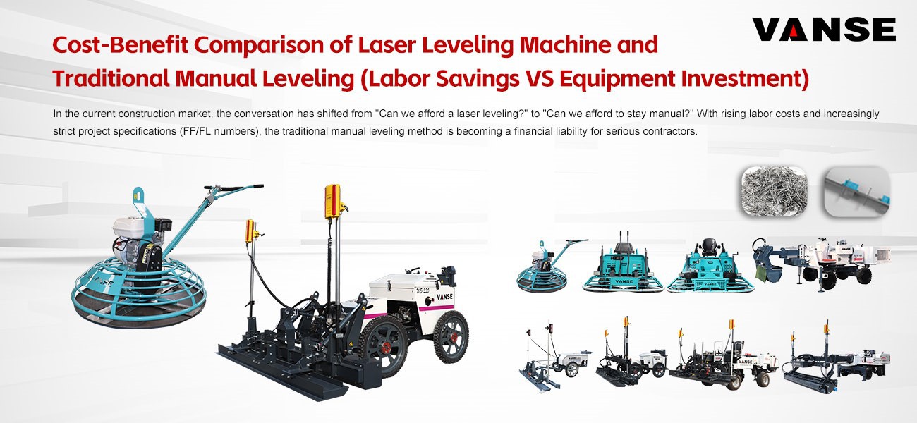
In the current construction market, the conversation has shifted from "Can we afford a laser leveling?" to "Can we afford to stay manual?" With rising labor costs and increasingly strict project specifications (FF/FL numbers), the traditional manual leveling method is becoming a financial liability for serious contractors.
If you’re weighing the Equipment Investment of a Vanse Concrete Laser Leveling Machine against the perceived "low cost" of manual labor, here is the professional breakdown of the real ROI.
1. The Productivity Gap: Square Meters per Hour
Manual leveling is slow, grueling, and dependent on the physical stamina of your crew.
Manual: A highly skilled 10-man crew might manage 600–800m² in a long, exhausting day.
Vanse Workflow: With a Vanse YZ25-4/YZ28-4S/WS940/WS940C or the telescopic YZ30-4E, that same crew (or even a smaller one) can easily cover 2,500–3,500m² per day.
The Math: You are essentially quadrupling your output. In the international market, where project timelines are aggressive, this speed allows you to take on 3x more projects per year with the same headcount.
2. Labor Savings: From 12 Men to 5
The "hidden cost" of manual leveling isn't just the hourly wage; it’s the insurance, the management, and the human error.
Manual: You need a massive team for distribution, leveling, and vibrating.
The Vanse Fleet Solution:
Replace 4 guys with shovels with one Vanse Concrete Distributor or a Mini Dumper.
Replace the 6-man leveling team with one Concrete Laser Leveling Machine operator.
Instead of manual "dusting," use an Automatic Topping Spreader to ensure uniform wear-resistance.
Result: You cut your specialized labor requirements by over 50%. In regions like North America or Europe, the machine often pays for itself in labor savings alone within 6–9 months.
3. Quality Control: FF/FL Scores and Rework
Manual leveling rarely hits the "Superflat" specs required for modern VNA warehouses.
The Risk: If a manual floor fails an FF/FL test, you face the nightmare of grinding or, worse, a "rip and replace" order.
The Vanse Guarantee: Vanse machines react to laser signals 10 times per second. By using a Vanse Power Trowel following the laser leveling, you achieve a "burnished" mirror finish that passes inspection the first time. Precision Concrete Cutting Machines from Vanse then ensure the joints are clean, preventing late-stage cracking.
4. Comparison Table: Manual vs. Vanse Ecosystem
| Metric | Traditional Manual Leveling | Vanse Laser Leveling System |
| Crew Size | 10–15 Workers | 4–6 Workers |
| Daily Output | 500 – 800 m² | 2,500 – 3,500 m² |
| Precision (FF/FL) | Low to Medium (Subject to fatigue) | High to Superflat (Consistent) |
| Physical Strain | Extremely High (High turnover) | Low (Operated via joystick/seat) |
| Surface Hardness | Uneven (Manual spreading) | Superior (Automatic Topping Spreader) |
| Long-term Cost | High (Labor + Rework risk) | Low (Maintenance + Depreciation) |
The "Vanse Ecosystem" Advantage
When you visit www.vansemac.com, you aren't just looking at a price tag; you’re looking at a business transformation tool.
The Concrete Distributor and Mini Dumper handle the heavy lifting.
The Laser Leveling Machine handles the precision.
The Topping Spreader and Power Trowel handle the durability.
The Concrete Cutting Machine handles the finish.
Final Verdict: Is it worth the investment?
If your business goal is to stay small and handle residential driveways, manual is fine. But if you want to bid on Amazon-scale warehouses, logistics hubs, or high-end industrial bays, the equipment investment in a Vanse fleet is the only way to remain competitive.
The investment isn't just in the steel and hydraulics; it’s an investment in guaranteed quality and massive labor efficiency.
Explore the full range and request a quote at www.vansemac.com to see how the numbers work for your specific market.
Note: The parameters provided in this document are for reference only and are not mandatory. Due to differences in technical characteristics between different brands and models of laser levelers, please consult the manufacturer for a suitable solution before actual operation. This reference document assumes no responsibility for any issues arising from failure to follow the manufacturer's instructions.
Thanks to All the Friends Who Support and Trust Shandong Vanse Machinery Technology Co., Ltd.
If you want to know more about Shandong Vanse Machinery Technology Co., Ltd. or have any questions, please feel free to contact us:
Our Factory
Shandong Vanse Machinery Technology Co., Ltd.








Share this article

About the Author: Shandong Vanse Machinery Technology Co., Ltd.
Shandong Vanse Machinery Technology Co., Ltd. is a high-tech manufacturer specializing in concrete construction machinery, including laser screeds and related equipment. The company integrates R&D, production, and global sales, with products exported to over 60 countries and widely used in infrastructure projects worldwide.
Previous Post
Next Post
Related Articles
You Might Also Like
When supplying antimicrobial mesh,how should the concentration of the antimicrobial mesh be determined?
– Different building structure types and usage functions have clear steel mesh spacing requirements in the design specifications. For example, for general concrete slab structures, according to the "Concrete Structure Design Code", the spacing of steel bars should not be less than 70mm, when the slab thickness is not more than 150mm, the steel bar spacing should not be more than 200mm; when the slab thickness is more than 150mm, the steel bar spacing should not be more than 1.5 times the slab thickness, and should not be more than 250mm. For structures with special requirements, such as basement top slabs, hydraulic structures, etc., the specifications may have stricter regulations. – Through structural mechanics calculations, determine the load size, distribution, and force transmission path of the concrete structure during use. According to the calculation results, the steel mesh is reasonably arranged to meet the bearing capacity and deformation requirements of the structure. For example, in a two-way slab subjected to a large bending moment, in order to effectively resist the bending moment in both directions, it is necessary to determine the spacing of the steel mesh in different areas according to the bending moment diagram. Generally speaking, in areas with large bending moments, the spacing of the steel mesh should be appropriately reduced to provide sufficient bending resistance; while in areas with small bending moments, the spacing of the steel mesh can be appropriately increased, but it must meet the minimum spacing requirements of the specification. – Consider the pouring method of concrete and the performance of the vibration equipment to ensure that the concrete can fully wrap the steel bars and vibrate densely during the pouring and vibration process. If the spacing of the steel mesh is too small, it will affect the fluidity of the concrete and the insertion of the vibrator, making it difficult to pour the concrete densely, and it is easy to have quality problems such as honeycombs and rough surfaces; if the spacing is too large, it will affect the restraint of the steel bars on the concrete and reduce the integrity of the structure. For example, when pumping concrete, due to the large fluidity of the concrete, the spacing of the steel mesh can be relatively small, but it is also necessary to ensure that the vibrator can be smoothly inserted for vibration. In general, in order to facilitate the operation of the vibrator, the net spacing of the steel mesh should not be less than 1.5 times the diameter of the vibrator. – Steel bars of different specifications and types have different bearing capacities and deformation properties, which will affect the determination of the spacing of the steel mesh. For example, high-strength steel bars can withstand greater tensile forces, and their spacing can be appropriately larger than ordinary steel bars on the premise of meeting the structural force requirements. For steel bars with larger diameters, in order to ensure sufficient bonding between the steel bars and concrete, and to avoid excessive concentration of steel bars leading to difficulties in concrete pouring, the spacing of the steel meshes also needs to be increased accordingly. Generally speaking, the larger the diameter of the steel bar, the larger the spacing of the steel meshes should be. For example, when using steel bars with a diameter of 10mm, the spacing may be 150-200mm; and when using steel bars with a diameter of 12mm, the spacing may be 180-250mm. In actual projects, the determination of the spacing of the steel meshes needs to be determined by professional structural engineers based on the specific project conditions, taking into account the above factors, through rigorous calculation and analysis, and following relevant design specifications and standards to ensure the safety, applicability and durability of the structure.Concrete laser leveling machine operation method
1. Preparation before operation of concrete laser leveling machine Before operating the concrete laser leveling, a series of preparations are required. First, you need to check whether all parts of the laser leveling machine are intact, including the engine, laser transmitter, scraper, etc. At the same time, you need to ensure that the power supply of the laser leveling machine is sufficient and the cables are intact. In addition, you need to prepare the required tools and materials, such as levels, elevation lines, sandpaper, etc. 2. Installation and debugging of laser leveling machine When installing the laser leveling machine, you need to follow the instructions. First, you need to place the laser leveler on a flat ground and make sure it is stable. Then, you need to connect the cables and check that the engine and laser transmitter are working properly. When debugging, the angle and height of the laser transmitter need to be adjusted to ensure that it can correctly scan the concrete surface. At the same time, the pressure and angle of the scraper also need to be adjusted to ensure a good scraping effect. 3. Operation process of laser leveling machine When operating a laser leveling machine, you need to follow a certain process. First, the concrete surface needs to be cleaned and elevation lines marked. Then, you need to start the laser leveling machine and adjust various parameters. Next, you need to use a scraper to smooth the concrete surface and use a level to check the flatness. If any uneven areas are found, they need to be re-scraped and inspected again. Finally, the surface needs to be sanded down to improve its finish. 4. Maintenance and maintenance of laser leveling machine In order to maintain the good working condition of the laser leveling machine, regular maintenance and upkeep is required. First of all, the laser emitter and scraper need to be cleaned regularly to avoid the impact of debris and dirt. At the same time, it is necessary to regularly check whether components such as cables and engines are working properly. If damage or aging is found, it needs to be replaced or repaired in time. In addition, critical parts need to be lubricated regularly to reduce friction and wear. 5. Common faults and troubleshooting methods of laser leveling machines During use, some common faults may occur with laser leveling machines. For example, the engine cannot start, the laser transmitter fails, the scraper does not scrape the compacted soil surface, etc. These faults need to be analyzed and dealt with based on specific circumstances. For example, if the engine fails to start, you may need to check whether the cables and the engine itself are working properly; if the laser transmitter fails, you may need to adjust its angle or height. In addition, equipment needs to be inspected and maintained regularly to prevent potential problems. 6. Safety precautions for laser leveling machines When using a laser leveler, you need to pay attention to safety issues. First of all, you need to ensure that the power cord is safe and reliable to avoid electric shock accidents. At the same time, it is necessary to wear protective glasses and other personal protective equipment during the operation to avoid damage to the eyes and other parts caused by splashed concrete and other debris. In addition, when handling and moving the laser leveling machine, you need to operate with caution to avoid accidents. 7. Sharing of skills and experience in using laser leveling machine When using a laser leveler, mastering some skills and experience can help improve work efficiency and quality. For example, when scraping the surface of compacted soil, you need to master the pressure and angle of the scraper: when adjusting the laser transmitter, you need to follow the principle of "first the whole and then the part"; when polishing the surface, you need to pay attention to the choice of sandpaper and Instructions. At the same time, experience can be continuously accumulated during use and adjustments can be made to better adapt to various working conditions and improve project quality. 8. Economic and cost-effective evaluation As a modern concrete construction equipment, laser leveling machine has significant economic and cost-effective advantages. Firstly, compared with the traditional manual smoothing method, using laser leveling machine can greatly improve work efficiency and reduce labor costs. Secondly, laser leveling machine has Better durability and stability reduce the cost of repair and maintenance. Finally, in the long run, using a laser leveler can improve the quality of the T process and reduce the cost of later maintenance and rework. Therefore, from the perspective of economy and cost-effectiveness, using concrete laser leveling machine Flat machines have higher value. 9. Precautions during concrete construction When using concrete for construction, you need to pay attention to the following points. First, you need to choose the appropriate cement variety and proportion to ensure the strength and quality of the concrete. Second, you need to control the mixing and transportation of concrete during the construction process to avoid segregation and initial setting. At the same time, it is also necessary to pay attention to the temperature and humidity control during construction to avoid problems such as shrinkage and cracking. Finally, adequate maintenance is required after the pouring is completed to ensure the quality of the mixer. 10. Relevant laws, regulations and standards When using concrete laser leveling machines, you need to comply with relevant laws, regulations and standards to ensure safety and quality. National and local laws and regulations on construction site safety management have clear provisions on the use and management of construction equipment. At the same time, during construction The technical requirements and operating procedures of laser leveling machines are stipulated in detail in the industry's standards and specifications for construction equipment and technology. Therefore, when using concrete laser leveling machines, you need to carefully study and abide by relevant laws, regulations and standards to ensure safety and quality. .How can one avoid excessive vibration when using a concrete laser leveling machine on a fiber-reinforced concrete floor?
Avoid excessive vibration when using a laser leveling machine on fiber concrete surfaces. The key lies in leveraging the adjustable features of the equipment and combining them with the material properties to manage the construction parameters in a refined manner. The laser leveling machine has already taken into account the construction requirements of fiber concrete during its design. All you need to do is master the correct adjustment methods, which will enable you to ensure the compactness while avoiding uneven fiber distribution or surface defects caused by excessive vibration. Here are the specific operation points for your reference: Objective: To prevent problems before they occur and promptly identify potential issues through daily observation. Control dimensions Specific operations and goals Why can excessive vibration be avoided? 1. Adjust the vibration frequency Adjust the exciter frequency to the recommended range (such as 3000-4000 times per minute) based on the type of fibers and the slump of the concrete. The goal is "full exhaust and uniform distribution", rather than "the longer the better". The workability of fiber concrete is different. The preset high-frequency vibration is sufficient to liquefy and densify it. If the frequency is too high or the duration is too long, it will cause the steel fibers to sink or the synthetic fibers to float, destroying the homogeneity. 2. Control the traveling speed of the leveling head Use a uniform and smooth moving method, avoiding staying at a certain point for too long. The goal is to complete the scraping, vibrating and leveling of the leveling head in one go, rather than repeatedly kneading. Moving at a constant speed ensures that the concrete receives uniform and appropriate vibration energy. Staying or moving too slowly is equivalent to local excessive vibration, which may cause "over-vibration" segregation. 3. Optimize the concrete mix ratio By adding water reducers and other methods, adjust the slump of the concrete to the optimal working range of the laser leveling machine (such as 14 ± 2 cm), rather than improving the fluidity by increasing the water volume. A concrete with good workability and no need for excessive vibration to level is itself the best defense against excessive vibration. It can reduce reliance on mechanical vibration. 4. Select the appropriate equipment type For concrete floors with high fiber content or those requiring special protection, consider using telescopic-arm type laser leveling machines. The operator operates on the completed ground, avoiding direct compaction of the newly poured concrete, thus fundamentally avoiding disturbance to the concrete structure. This "construction from the outside" method completely eliminates the compression and disturbance of unset concrete caused by equipment movement and vibration, and is an advanced technique for achieving high-quality fiber concrete floors. During the construction process, several signs can be observed to determine whether the vibration is appropriate: Surface condition: After vibration, the surface should quickly develop a coating of concrete. If there is a large amount of cement slurry rising while the aggregates sink (layering and segregation), it is a clear sign of over-vibration. Fiber condition: If large areas of steel fibers are exposed or concentrated on the surface, or if synthetic fibers form clumps and rise, it indicates that the vibration energy is too high or the duration is too long, which has disrupted the three-dimensional distribution network of the fibers. Edge stability: After leveling, the edges of the concrete should maintain a stable shape. If there is collapse or flowing at the edges, it indicates that the vibration was excessive, causing the concrete to have excessive fluidity. A very effective approach is to reduce the reliance on post-construction vibration through optimized design. For instance, in warehouse or large industrial flooring projects, using macroscopic synthetic fibers instead of traditional steel mesh can offer the following advantages: After the concrete is unloaded from the mixer, it can be directly spread without the need for workers to pre-bolt the steel mesh. When the laser leveling machine is in operation, there is no need to worry about scratching or disturbing the steel mesh, thus allowing the leveling head to pass through more smoothly and quickly, reducing pauses and local excessive vibration caused by avoiding the steel mesh. As stated in actual projects, this "eliminates hundreds of hours of labor and completes reinforcement while pouring the concrete, providing a better slab structure". The core of avoiding excessive vibration lies in "accuracy" rather than "power". By precisely adjusting equipment, optimizing material performance, and combining advanced construction methods, it is entirely possible to utilize the efficient advantages of the laser leveling machine to create a dense, flat, and high-quality fiber concrete floor. What type of fibers are used in your project – steel fibers or synthetic fibers? Different types of fibers have different sensitivity to vibration. Please tell me the specific type so that I can provide you with more targeted vibration parameter suggestions. Contact us NOW Note: The parameters provided in this document are for reference only and are not mandatory. Due to differences in technical characteristics between different brands and models of laser levelers, please consult the manufacturer for a suitable solution before actual operation. This reference document assumes no responsibility for any issues arising from failure to follow the manufacturer's instructions.