Technical Knowledge
With the advent of laser leveling machines, are you still using the old vibrating leveler to vibrate the beam?

With the advent of laser leveling machines, are you still using the old vibrating leveler to vibrate the beam?
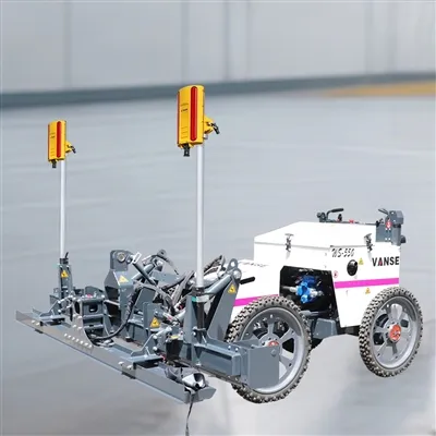
When it comes to construction, everyone knows that only with a short construction period and high quality can we save costs, improve efficiency and increase profits. If you want to save costs quickly during construction, construction tools are a very important choice. An efficient, convenient and fast tool will make construction work more effective with half the effort! On the contrary, choosing inappropriate tools will extend the construction period, increase costs, and reduce profits. Take the floor construction under construction as an example! The flatness of the floor is more difficult to grasp. Leveling is usually done manually. Even if you use an old-fashioned floor machine, the effect and cost are not particularly ideal. The emergence of a laser leveling machine has greatly solved many problems that arise during construction. During the construction process, it can solve the problems of hollowing, shelling, cracking, and uneven ground after general construction. It can make the final effect exceed Party A's floor quality requirements, reduce costs, and Improved work efficiency.
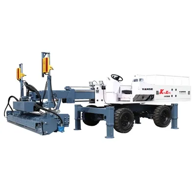
Many industries require factories, as well as shopping malls, large warehouses and other construction sites that require large areas of ground, to have much higher standards. Attention has been greatly increased to the strength, flatness and level of the ground quality. It is difficult to meet the requirements using old-fashioned flooring methods, and labor costs will increase exponentially. The construction principle of the laser leveler is very simple and clear. It can perform several construction processes such as leveling and vibration at the same time, further ensuring the quality of the construction and completely saving labor costs. The advantage of construction is that the construction speed is fast and the quality is high, ensuring that the overall integrity of the ground is good and cracks are not prone to occur. The amount of support and disassembly is reduced compared with the traditional method. Moreover, the reduction in the number of workers ensures an increase in final profits.
Thanks to All the Friends Who Support and Trust Shandong Vanse Machinery Technology Co., Ltd.
If you want to know more about Shandong Vanse Machinery Technology Co., Ltd. or have any questions, please feel free to contact us:
Our Factory
Shandong Vanse Machinery Technology Co., Ltd.








Share this article

About the Author: Shandong Vanse Machinery Technology Co., Ltd.
Shandong Vanse Machinery Technology Co., Ltd. is a high-tech manufacturer specializing in concrete construction machinery, including laser screeds and related equipment. The company integrates R&D, production, and global sales, with products exported to over 60 countries and widely used in infrastructure projects worldwide.
Previous Post
Next Post
Related Articles
You Might Also Like
How does the construction technology and construction process of concrete laser leveling machine ensure construction quality?
The concrete laser leveling machine combines "precision control + standardized processes," from construction process design to full-process management and control, systematically addressing core quality issues such as concrete surface flatness, density, and thickness uniformity. Its quality assurance logic can be broken down into two components: process principle assurance and full-process management and control. The details are as follows: The quality advantage of the concrete laser leveling machine stems from its unique process design. Its core technology replaces traditional manual wire drawing with "laser reference positioning," combined with a "hydraulic-driven leveling mechanism" to achieve millimeter-level precision control. Key process details are as follows: Principle: A laser transmitter (rotatable 360°) establishes a horizontal reference plane. A laser receiver (mounted on the leveling frame) receives the signal in real time. If the machine deviates from the reference plane, the control system immediately activates the hydraulic cylinder to adjust the frame height, ensuring that the leveling mechanism always operates within the reference plane. Quality Assurance: This eliminates the "segmental errors" associated with traditional manual wire drawing (e.g., height differences caused by wire slack and line of sight deviation). The reference surface covers a range of up to 50 meters, with a global flatness error of ≤3mm/2m (far exceeding the 5-8mm/2m error of traditional methods). A laser transmitter can be used to preset slopes (0.1%-5%), enabling precise drainage slope construction and preventing subsequent water accumulation (e.g., drainage needs in garages, rooftops, and factory floors). Leveling Mechanism: Utilizes a "spiral blade + scraper" combination. The spiral blades first evenly spread the concrete (controlling the amount of concrete spread based on the preset thickness), followed by the scraper for preliminary leveling to prevent spot buildup or missed vibrations. Vibration System: The machine is equipped with a high-frequency vibrator (vibration frequency 2000-3000 times/minute), capable of vibrating to a depth of 150-300mm (adjusted based on concrete thickness). Compared to manual vibration: More uniform density: High-frequency vibration effectively removes air bubbles from the concrete, preventing honeycombing and rough surfaces, and can increase the concrete's compressive strength by 10%-15%. Preventing "over-vibration segregation": The control system automatically adjusts the vibration frequency to match the concrete slump (e.g., for a slump of 120-180mm, the frequency is set to 2500 times/minute), preventing aggregate sinking and mortar floating, which can cause surface sanding. The leveling machine utilizes "four-wheel drive + intelligent travel" technology. Its travel speed can be adjusted (0.5-1.5 m/min) based on the initial setting time of the concrete (typically 2-4 hours) and the construction area. This avoids: Traveling too fast, resulting in uneven distribution and incomplete leveling; Traveling too slowly, resulting in disturbance of the concrete after initial setting, causing cracks or peeling. For large-scale construction (such as factories and logistics warehouses), a "zoned skipping method" is used. A 100-150 mm wide "post-pouring strip" is reserved at the zone boundaries to prevent cracking caused by thermal stress. Quality cannot be fully guaranteed through process design alone. Standardized process control is required to cover key quality milestones throughout the construction cycle: Preparation Core Requirements Quality Impact Base preparation 1. The flatness tolerance of the base layer (e.g., subgrade, roadbed) must be ≤5mm/2m. Protrusions and depressions must be manually repaired. If the base layer is uneven, a laser leveling can control the surface layer, but this can lead to uneven concrete thickness (thin areas can cause cracking, while thick areas increase costs). A dry base layer can cause rapid water loss from the concrete surface, resulting in sanding. 2. The base layer surface must be moistened with water (moisture content 10%-15%) to prevent moisture absorption from the concrete and cracking. Laser system calibration 1. The laser transmitter must be mounted on a stable support (away from vibration sources such as rollers). Laser system deviation is a "hidden quality issue" that can cause the leveling layer to tilt (for example, a garage with a reversed drainage slope), leading to extremely high rework costs. 2. Use a 2m straightedge and a level to calibrate the laser reference surface to an accuracy of ≤1mm. Concrete mix control 1. Slump: 50-100mm (for dry, hard concrete to avoid run-off after leveling). Excessive slump: Concrete tends to segregate, resulting in sanding. Excessive slump: The leveling has difficulty leveling, resulting in poor vibration compaction and honeycombing. 2. Aggregate Grading: Coarse aggregate (5-25mm) should account for 60%-65%, and fine aggregate (0.3-5mm) should account for 30%-35%. Avoid excessive coarse aggregate, which can cause surface unevenness. Material Distribution Control: Concrete must be distributed directly to the construction site via a chute or pump. The distribution height should be 50-80mm above the intended surface layer (allowing for leveling margins) to prevent aggregate separation caused by manual shoveling. The leveling machine must be started within 30 minutes of distribution to prevent initial setting of the concrete (in summer, this time should be shortened to 20 minutes; shade cloth can be used to delay initial setting). leveling Machine Operating Specifications: The operator must monitor the laser receiver indicator light (green: normal, red: deviation from the reference). If a red light appears, immediately stop the machine and inspect the laser system (for obstructions or transmitter offset). For every 100 square meters of surface area leveled, use a 2-meter ruler to randomly check 3-5 points. The flatness deviation must be ≤3mm. If it exceeds this standard, immediately adjust the laser reference or machine parameters. Surface Finishing: After laser leveling, wait for the concrete surface to initially set (no noticeable indentation when pressed with a finger, approximately 1-2 hours). Then, use an electric trowel to apply finishing (1-2 passes) to eliminate surface bubbles and scratches and improve surface smoothness (to prevent later sanding). When finishing, avoid staying in one spot for too long to prevent "smear marks" on the surface. Stage 3: Post-construction Curing (to prevent later quality defects) Cover Curing: Within 1-2 hours after finishing, cover the concrete with geotextile or plastic film to ensure the surface is moist (avoid direct sunlight or strong winds). During high summer temperatures, water the geotextile every 2-3 hours to keep it moist. During low winter temperatures, cover with insulation (when ambient temperature is ≤5°C, use floor heating or hot air curing to prevent freezing damage). Curation Cycle: The curing period for ordinary concrete (C30-C40) is ≥ 7 days; the curing period for high-strength concrete (C50 and above) is ≥ 14 days. During the curing period, personnel and vehicles (especially heavy vehicles) are prohibited from passing through to avoid surface indentations or cracks. Joint cutting and caulking: After 3-5 days of curing, use a joint cutter to cut shrinkage joints (spaced 6-8 meters apart and 1/3-1/4 the concrete thickness) to prevent irregular cracking caused by thermal stress. Within 24 hours of cutting, fill the joints with polyurethane sealant to prevent rainwater from seeping into the base layer, which could cause hollowing and peeling of the surface layer. Even if the process is strictly followed, unexpected quality issues may still occur and require prompt attention: Cause: Dry base layer, poor curing, and delayed crack cutting. Solution: If the crack width is ≤ 0.3mm, fill with epoxy resin. If the crack width is > 0.3mm, cut a 10mm wide and 20mm deep groove, fill with sealant, and re-finish. Cause: Laser system offset, uneven distribution of concrete. Solution: If the concrete has not initially set (within 1 hour of pouring), recalibrate the laser system and perform a second leveling. If it has already set, manually remove any raised areas with an angle grinder and then level with repair mortar. Cause: Improper concrete mix (excessive fine aggregate) and inadequate curing. Solution: Apply a "concrete sealer and hardener" to the surface (penetration depth 3-5mm) to increase surface hardness (Mohs hardness up to 6-7) and prevent sanding. The quality assurance principle for concrete laser leveling machines is "precision technology + standardized processes." In terms of technology, laser positioning eliminates manual errors, and high-frequency vibration ensures compaction, reducing quality defects at the root. In terms of process, pre-calibration, in-process testing, and post-process maintenance form a closed-loop quality loop, avoiding late-stage rework caused by "hidden issues" (such as laser offset and insufficient curing). Only by combining these two methods can a high-quality concrete surface layer with high flatness, excellent density, and no cracks or sanding be achieved. Note: The parameters provided in this document are for reference only and are not mandatory. Due to differences in technical characteristics between different brands and models of laser levelers, please consult the manufacturer for a suitable solution before actual operation. This reference document assumes no responsibility for any issues arising from failure to follow the manufacturer's instructions.Technical tips for leveling the power trowel chassis and calibrating the blade height consistency
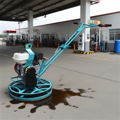
The construction quality of a power trowel (also known as a finishing machine) is 70% about leveling and 30% about operation. The flatness of the chassis and the blade is the key to determining whether the concrete surface ultimately achieves a mirror-like smoothness, without ripples or flaws. The following are detailed technical tips for leveling the base of a power trowel and calibrating the consistency of the blade height, combining the experience of experienced masters with scientific methods. One benchmark: Take the chassis as the sole benchmark. All blade adjustments must be based on a already leveled chassis. Three unifications: uniform blade height, uniform inclination Angle, and uniform wear degree. The chassis serves as the installation platform for the blade. If the chassis itself is uneven, the consistency of the blade is out of the question. First choice: A large and flat platform (such as a calibrated granite platform, a thick tempered glass tabletop or a new thick steel plate). Second choice: On a very flat ground, use a known uniform thickness pad (such as a feeler gauge). Essential items: feeler gauge, tape measure, marker pen. Cleaning and preparation Thoroughly clean the chassis and remove all cement slurry and hard lumps. Check the chassis for any obvious deformation caused by the collision. If there is severe deformation, it needs to be corrected or replaced first. Place the power trowel on the platform and ensure that the contact surface between the chassis and the platform is clean and free of debris. Preliminary "Four-point measurement Method" Consider the chassis as a clock face and measure the gap between the edge of the chassis and the surface of the platform at the four positions of 12 o 'clock, 3 o 'clock, 6 o 'clock and 9 o 'clock. Use a feeler gauge to measure and record the gap values at four points. Preliminary judgment: If the gap values at the four points differ by more than 1-2 millimeters, it indicates that the chassis is uneven and needs to be adjusted. The chassis of most power trowels is connected to the main unit through three or four adjustable pull rods. Identify the high and low points: Based on the measurement data, determine which corner has the smallest clearance (the highest point of the chassis) and which has the largest clearance (the lowest point of the chassis). To raise a certain Angle, loosen (counterclockwise) the lock nut of the pull rod corresponding to that Angle, then shorten the length of the pull rod (turn the pull rod body clockwise), and finally tighten the lock nut. To lower a certain Angle, loosen the lock nut, then extend the length of the pull rod (turn it counterclockwise), and finally lock it. The mnemonic: "High pines are short, low pines are long." (For the angles that need to be adjusted After each adjustment, gently rotate the chassis (to prevent scratching the platform) and conduct the four-point measurement again. Repeat steps 3 and 4 until the difference in gap values among the four points is controlled within 1 millimeter. At this point, it can be considered that the chassis has been leveled. The calibration of the blade can only be carried out on the basis of ensuring that the chassis is absolutely flat. A ruler (preferably a high-precision steel ruler) or a dedicated blade height gauge. Tape measure, marker pen, wrench. Installation and cleaning Install a set of blades of consistent newness and oldness onto the blade seat. It is strictly prohibited to mix new and old blades! Make sure that all the blade fixing bolts and blade seats are clean, the threads are undamaged and can be tightened in place. Place the power trowel with the chassis adjusted on a flat ground. Place a fixed reference point (such as a thin gasket or directly using the joints of floor tiles) on the ground beneath the chassis and within the rotation trajectory of the blade. Stand a ruler vertically beside the reference point and measure the distance from one of the knife tips to the ground, recording it as the reference height H. It is extremely important: Manually and slowly rotate the base of the trotter so that the same position of the next blade (for example, the outermost end of both blades) rotates directly above the reference point. Measure the distance from the tip of the knife to the ground again with a ruler. Compare it with the reference height H and record the difference. For example: Blade 1 is H, blade 2 is H-1.5mm, and Blade 3 is H+1.0mm. Measure all the blades in sequence. The height of the blade is adjusted by the regulating bolt on the blade seat to change its inclination Angle. Adjustment principle If the measured value of a certain blade is low, it needs to be raised. The method is: tighten the adjusting bolt below the blade seat, or loosen the adjusting bolt above to lift the leading edge of the blade (the side close to the rotation direction). If the measured value of a certain blade is too high, it needs to be reduced. The method is: Loosen the adjusting bolt below the blade seat or tighten the adjusting bolt above it to lower the leading edge of the blade. Mnemonic: "High tight, low loose, the leading edge as the standard." (For the leading edge of the blade that needs to be adjusted After adjusting each blade, it is necessary to rotate and measure once again, as adjusting one blade may slightly affect the height of adjacent blades. Repeat steps 3 and 4 until the difference between the measured height of all blades at the reference point and the reference height H is controlled within ±1 millimeter. Final inspection: Rotate the chassis quickly and listen to the sound with your ears. When the highly uniform blades are idling, the wind sound is a uniform "buzz". Inconsistent ones will have a periodic noise of "puff puff". The sequence is crucial: the chassis must be leveled first, and then the blades calibrated. Reversing the order is in vain. Tools are the guarantee: Having an absolutely flat calibration platform is half the battle. Data-driven operation: Trust feeler gauges and rulers, not rely on the naked eye. Each adjustment should be measured and recorded. Complete set replacement: The blades must be replaced as a complete set to maintain the same wear condition. Regular inspection: A quick inspection should be carried out before starting work every day and after replacing the blade. A full set of calibration should be carried out every 50 to 100 hours of operation or after a collision. Safety first: All operations must be carried out when the machine is completely powered off and the engine is turned off. Through the above strict and meticulous process, your power trowel machine will be in the best working condition, capable of easily creating a mirror-like smooth and high-quality concrete surface, effectively avoiding problems such as ripples, scratches and excessive cutting, thereby enhancing construction efficiency and professional image. Note: The parameters provided in this document are for reference only and are not mandatory. Due to differences in technical characteristics between different brands and models of laser levelers, please consult the manufacturer for a suitable solution before actual operation. This reference document assumes no responsibility for any issues arising from failure to follow the manufacturer's instructions.Four reasons for you to choose the laser leveling machine!
We chose the laser leveling machine because it is fast in leveling and highly automated. After the height is adjusted manually, the machine can operate automatically. It integrates leveling, leveling, tamping and compaction. All work can be completed at one time, which is very suitable for the leveling needs of large sites. (1) The leveling principle of the laser leveling machine is to use precision laser technology, closed-loop control technology and highly precise hydraulic system, which is realized under the automatic control of the computer. This is its most prominent feature that distinguishes it from other floor construction processes. (2) The leveling principle of the laser leveling machine is to rely on the hydraulically driven leveling head, cooperate with the laser system and computer control system to complete the leveling work while automatically leveling. The leveling head is equipped with an integrated scraper, vibrator and leveling plate, which integrates all leveling, leveling, vibrating and compacting work and completes it at one time. The computer control system automatically adjusts the elevation in real time 10 times per second, and the vibration frequency of the balanced vibrator reaches 3000 times/minute. (3) The laser transmitter used to control the ground elevation is arranged independently, so that the floor elevation is not controlled by the template and no cumulative error will be generated. (4) The laser leveling machine can also automatically control the longitudinal and transverse slopes, which is also completed by the laser system, computer system, hydraulic system, and mechanical system. For complex-shaped floors with high requirements such as drainage, a three-dimensional special-shaped floor processing system can also be selected to achieve it. The laser leveling machine is developed based on the increasing demand for floor quality such as strength, flatness, and levelness in modern industrial plants, large shopping malls, warehouses, and other large-area cement concrete floors. The cement concrete floor paved and leveled by the Shenlong laser leveling machine is much better than the floor paved by conventional methods – the flatness and levelness of the floor are improved by more than 3 times, and the density and strength are improved by more than 20%. At the same time, it can also improve work efficiency by more than 50% and save about 35% of labor. In addition, it can easily lay high-strength concrete, low-slump concrete, and fiber concrete. Its laser system is equipped with a variety of automatic control components, which monitor the elevation of the leveling head in real time at a frequency of 10 times per second to ensure that the flatness and levelness of the paved ground are effectively controlled. At the same time, its powerful vibrator has a vibration frequency of 3,000 times per minute to ensure that the concrete is vibrated and compacted, making the entire paved concrete matrix homogeneous and dense.