Technical Knowledge
Concrete show south east Asia Indonesia & Construction Indonesia
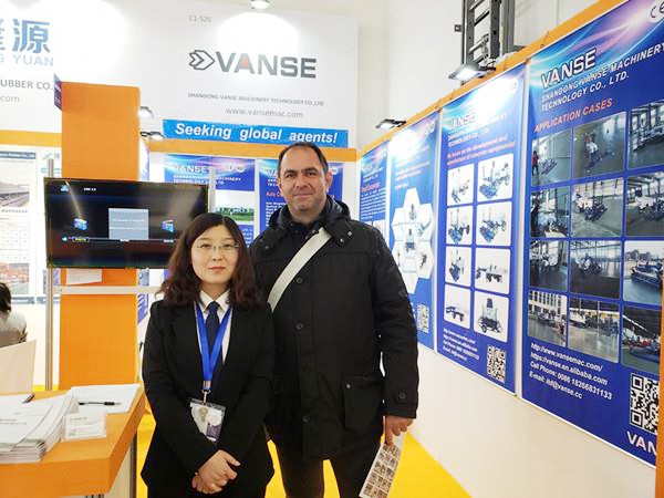
Concrete show south east Asia Indonesia & Construction Indonesia
time:13th Sep to 16th Sep, 2017
Booth: D2 HALL, C3-1
Will welcome the majority of friends visit the site visit
Thanks to All the Friends Who Support and Trust Shandong Vanse Machinery Technology Co., Ltd.
If you want to know more about Shandong Vanse Machinery Technology Co., Ltd. or have any questions, please feel free to contact us:
Our Factory
Shandong Vanse Machinery Technology Co., Ltd.








Share this article

About the Author: Shandong Vanse Machinery Technology Co., Ltd.
Shandong Vanse Machinery Technology Co., Ltd. is a high-tech manufacturer specializing in concrete construction machinery, including laser screeds and related equipment. The company integrates R&D, production, and global sales, with products exported to over 60 countries and widely used in infrastructure projects worldwide.
Previous Post
Next Post
Related Articles
You Might Also Like
A comprehensive understanding of the components of high performance concrete laser leveling
The laser leveling machine can bring us many advantages when it is used. I believe that all the friends who have used it should have realized it. Although everyone is very comfortable when operating the leveling machine, it is necessary to talk about the laser leveling machine. The components, then many friends are not clear, it seems that everyone is not careful enough about the leveling machine, the following article will lead everyone to learn more about the components of the laser leveling machine. Vanse boomed laser leveling machine Components of the laser leveler: 1. Steering system: It consists of steering wheel, steering gear, steering knuckle, steering knuckle arm, tie rod and straight rod. The function is steering. Battery: The function of the battery is to supply power to the starter, and to supply power to the engine ignition system and other consumers during engine start or low speed operation. When the engine is running at high speed, the generator generates enough power and the battery can store excess power. Hydraulic brake structure: The hydraulic brake device consists of a brake pedal, a master cylinder, a sub-pump, a drum (wheel) brake and a fuel pipe. 2. Motor: The motor is the power unit of the laser leveling machine. Its main function is to generate drive torque as a power source for electrical appliances or various machines. Its main function is to use mechanical energy to convert into electric energy. At present, it is more common to use heat energy, water energy, etc. to drive the generator rotor to generate electricity. 3. Transmission: It is composed of transmission case, transmission cover, first shaft, second shaft, intermediate shaft, reverse shaft, gear, bearing, operating mechanism, etc. It is used for variable speed and variable output torque of laser leveling machine. 4, leaf springs and shock absorbers: the role of leaf springs is to maintain a flexible connection between the frame and the body and the wheel or axle. The function of the shock absorber is to moderate the vibration when the laser leveler is subjected to shock. 5. Transmission system: It is mainly composed of transmission, universal joint, transmission shaft and drive axle. 6, driving system: consists of the frame, axle, suspension and wheels. Its basic function is to support the quality of the whole car and to ensure the driving of the laser leveler. 7. Starter: Its function is to convert electrical energy into mechanical energy, drive the crankshaft to rotate, and start the engine. If the continuous starting time is too long, it will cause a large discharge of the battery and the starter coil will overheat and smoke, which will easily damage the laser leveling machine.The Impact of Power Trowel Blade Angle and Speed on Surface Compactness
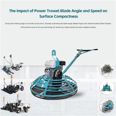
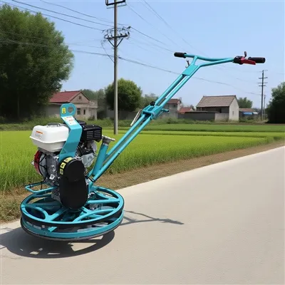
During the finishing stage of concrete construction, precisely controlling the blade angle (Blade Angle) and rotational speed (Rotor Speed) of the power trowel is the core technology for achieving a highly dense and wear-resistant surface. The blade angle (Blade Angle) determines the "pressing force": The physical mechanism is that the smaller the contact area, the greater the pressure. A small angle (such as 0° – 5°) causes the blade to almost lie flat on the ground, used for the initial leveling and slurry removal; as the concrete hardens, the angle needs to be gradually increased (such as 10° – 30°), so that the blade applies high pressure in a "cutting" posture, forcefully closing the capillary pores and squeezing out excess water and air, achieving densification. Studies have shown that correctly setting the blade angle can increase the compressive strength of the concrete surface by up to 15%. The rotational speed (Rotor Speed) determines the "operation frequency": The logic is the combination of kinetic energy and thermal effect. Low speed (50 – 90 RPM) is used in the initial stage to avoid disturbing the unstable surface; medium-high speed (100 – 150 + RPM) is used in the fine troweling stage, generating micro heat and high-frequency friction, promoting the rapid densification of the surface cement paste, forming a high-gloss "hard shell". Combining with the product knowledge base on Vanse Machinery's official website, the specific practical parameters and equipment support are as follows: Coarse scraping stage: Set the blade angle to 10° – 15°, and operate at a low speed (300 – 400 rpm) to remove loose mortar and small protrusions. Fine scraping stage: Gradually increase the angle to 25° – 30° and increase the speed to a medium-high speed (400 – 600 rpm) to enhance the surface density and gloss. For special requirements such as ultra-smooth floors, the angle can be adjusted to 30° – 45° during the final polishing. High-speed "polishing" stage: To achieve a "mirror-like" effect, maximize the blade angle (usually 20° – 30°) and speed, generate local heat through high-speed friction, and achieve the physical ultimate densification of the surface. High-grade/low water-cement ratio concrete (C40 and above): Sets quickly, with a short window period. The initial speed should be introduced earlier, using medium-low speed (approximately 60-80 RPM); during fine troweling, increase to medium-high speed (approximately 90-120 RPM), and gradually increase the blade angle (approximately 5-10°) to implement "cutting-style" polishing. Concrete containing retarders (summer/ large-scale construction): Sets slowly, requiring patience to build up support force. Initially, use low speed (approximately 50-70 RPM) to steadily scrape the surface; for subsequent polishing, maintain medium-low speed throughout to avoid "waveing" or "skinning" on the surface. Core adjustment principle: Just as emphasized in the Vanse technical documentation, "Observation is more important than presetting", there are no fixed values for parameters. The only standard is the immediate state of the concrete surface. Construction personnel should follow the principle of "from low speed to high speed, from small angle to large angle", and make dynamic adjustments. Too small angle: Leads to insufficient compaction, presence of pores on the surface, and reduced strength.应及时 increase the angle and accelerate the troweling during the fine troweling stage to make up for it. Too large angle: May scratch the hardened concrete surface or cause the machine to "chatter" and uneven wear. Should immediately reduce the angle and increase the walking speed. Inconsistent speed: If the initial speed is too fast, it will tear the surface and damage the flatness; if the later speed is too slow, it will result in insufficient compaction and dull luster. The blade angle and rotation speed are the core variables for the power trowel machine to achieve a dense concrete surface. By combining the precise staged parameters recommended by the Vanse Machinery website (rough troweling 10°-15°/300-400 RPM, fine troweling 25°-30°/400-600 RPM), and following the dynamic adjustment principle of "observation is more important than presetting", the construction team can effectively improve the construction quality and operational efficiency of the ground project. For more detailed trowel machine models and operation guidelines, you can directly visit the Vanse Machinery website or contact its technical team via email [email protected]. Note: The parameters provided in this document are for reference only and are not mandatory. Due to differences in technical characteristics between different brands and models of laser levelers, please consult the manufacturer for a suitable solution before actual operation. This reference document assumes no responsibility for any issues arising from failure to follow the manufacturer's instructions.Key points for lubrication & maintenance of the power trowel machine
Lubrication and maintenance of the power trowel is the core work to ensure the long-term stable operation of the equipment and prevent sudden failures. The key lies in "using the right oil, finding the right time, doing it on time and using the right method". The following are the specific key points 1. Power trowel the main shaft bearing – the most crucial and frequent Location: The center drive shaft of the pan, usually with 1-2 grease nozzles. Lubricant: High-temperature resistant (≥120℃), extreme pressure lithium-based grease (such as molybdenum disulfide grease) must be used. Ordinary butter must not be used. Method and Cycle It must be carried out after each shift's work (working for 8 to 10 hours). Thoroughly clean the grease nipple and its surroundings. Add until the new grease overflows: Use a grease gun to add until the clean new grease is completely squeezed out from the edge of the bearing seal ring from the old grease. Wipe off the excess grease. Objective: To remove metal shavings and impurities produced by internal wear and ensure that the bearing cavity is filled with new grease. 2. Gearbox/reducer Lubricant: Select the specified type of gear oil (such as SAE 80W-90 GL-4) strictly in accordance with the instructions. Check: Every day, check through the oil window or dipstick whether the oil level is between the upper and lower marks. Replacement cycle First replacement: After the new machine has been running for 20 to 30 hours, remove the running-in debris. Regular replacement: Replace it every 300 to 500 hours of operation or annually thereafter. Key point: Oil change should be carried out when the oil temperature is still hot after the equipment is shut down to ensure that the old oil is completely drained. 3. Traveling wheels and steering mechanism Location: Walking wheel bearing, steering tie rod ball joint, hinge point. Lubricant: The high-temperature resistant lithium-based grease as mentioned above. Cycle: Every 50 hours of operation or once a week. Method: Clean each grease nozzle and add grease until new grease overflows from the gaps. 4. Engine (Gasoline model) Engine oil inspection and replacement Check the oil dipstick before starting every day to ensure the oil level is normal. First replacement: After running for 20 to 30 hours. Regular replacement: Every 100 hours or every quarter. The cycle should be shortened in harsh environments. Air filter maintenance: Regular cleaning. For oil bath air filters, use the dedicated air filter oil as per the instructions. Cleaning first: Before filling, be sure to clean the oil nozzle, oil cap and the surrounding area to prevent sand, dust and concrete particles from being brought into the interior. Strict specifications: Different parts should use the specified type of grease/oil products. They must not be mixed or substituted. High-temperature grease is the "life-saving oil" for the main shaft bearings. Squeezing out the old grease: For bearing lubrication, "adding until the new grease overflows" is a necessary step. This is the only effective way to remove contaminants and ensure the lubrication effect. Precise cycle: The maintenance cycle is mainly based on the operating hours (rather than calendar time) and is strictly recorded. Error: Lubricate the main shaft bearings with ordinary grease. Consequence: The grease melts and leaks away at high temperatures, the bearings dry grind rapidly and burn out at high temperatures, leading to the failure of the entire machine. Error: Only add fat without squeezing out the old fat. Consequence: Metal shavings accumulate in the bearing cavity, forming abrasives, accelerating wear, and causing abnormal noises and jamming. Error: Ignoring the oil level in the gearbox and its replacement. Consequence: Insufficient lubrication of gears and bearings leads to pitting corrosion, broken teeth, and scrapping of the reducer. Error: The spilled grease was not cleaned up after lubrication. Consequence: Grease adsorbs dust to form hard scale, which damages the sealing performance of the oil seal and makes it easier for impurities to invade. Create a lubrication chart: Make a simple chart of all lubrication points, oil types and cycles of the equipment, and stick it in a prominent place on the equipment. Equipped with dedicated tools: Use high-quality grease guns and dedicated oiling nozzles to ensure sufficient filling pressure. Record: After each maintenance, record the operating hours and maintenance items to form a traceable maintenance file. Long-term storage and maintenance: Before the equipment is out of use, thoroughly lubricate all lubrication points once. The engine oil should be changed or stabilizers added as per regulations to prevent internal rusting. The lubrication and maintenance of a power trowel essentially involve the continuous confrontation with its harsh working environment (heavy load, high temperature, and much dust). By grasping the two key points of "post-shift high-temperature grease extrusion lubrication" for the main shaft bearings and "regular oil change" for the gearboxes, the vast majority of major mechanical failures can be avoided, significantly extending the service life of the equipment. Note: The parameters provided in this document are for reference only and are not mandatory. Due to differences in technical characteristics between different brands and models of laser levelers, please consult the manufacturer for a suitable solution before actual operation. This reference document assumes no responsibility for any issues arising from failure to follow the manufacturer's instructions.