Technical Knowledge
List of Common Quality Defects and Countermeasures in Super Flat Floor Construction
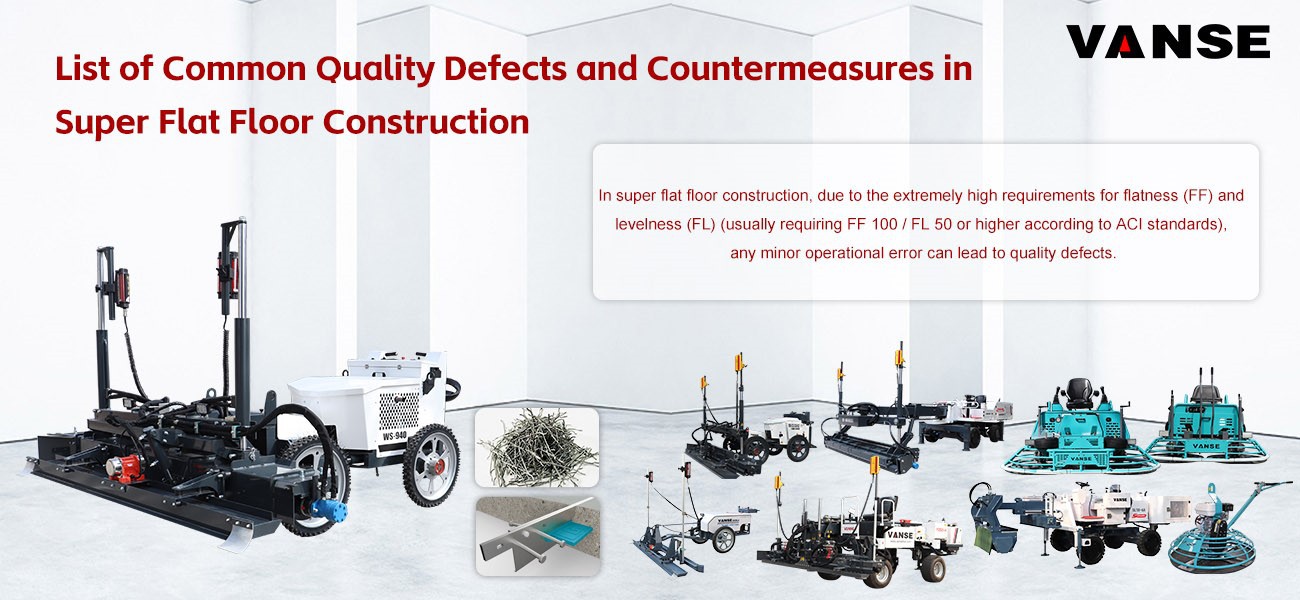
In super flat floor construction, due to the extremely high requirements for flatness (FF) and levelness (FL) (usually requiring FF 100 / FL 50 or higher according to ACI standards), any minor operational error can lead to quality defects.
The following is a list of common quality defects and their countermeasures in super flat floor construction:
1. Failure to meet flatness and levelness standards (FF/FL)
This is the most critical quality issue for super-flat floors.
Phenomenon: The floor surface has excessive undulations, preventing the smooth operation of narrow-aisle forklifts (VNA).
Reasons:
Unstable installation of side forms (channel steel) or errors in elevation control.
Laser Leveling signal interference or inaccurate sensor calibration.
Excessive fluctuations in concrete slump, leading to uneven shrinkage during the hardening process.
Countermeasures:
High-precision formwork: Use high-rigidity channel steel and use a total station and level to re-measure, controlling the error within ± 1mm.
Digital monitoring: Use an F-Number measuring instrument (such as a Dipstick) for real-time monitoring during construction.
Material consistency: Strictly control the slump of concrete delivered to the site; the fluctuation range should be within ± 20mm.
2. Concrete Surface Cracks (Shrinkage Cracks)
Phenomenon: Irregular cracks or deep penetrating cracks appear on the surface several days or weeks after construction.
Causes:
Excessive water-cement ratio.
Delayed saw cutting, leading to concentrated release of internal stress.
Inadequate curing, resulting in rapid evaporation of surface moisture.
Countermeasures:
Optimize the mix design: Increase aggregate size, reduce cement paste volume, and add shrinkage-reducing admixtures.
Timely saw cutting: Use a "early-age saw cutting machine" (Soff-Cut) immediately after the concrete reaches initial setting strength (usually within 4-12 hours).
Strengthen curing: Immediately after finishing the surface, spray a high-concentration curing agent, or cover with a film for water curing for at least 7 days.
3. Surface Dusting and Peeling (Insufficient Surface Strength)
Phenomenon: Surface powdering occurs after forklift traffic, or the top layer of the hardening agent peels off.
Causes:
Excessive bleeding during the Leveling process, resulting in a high water-cement ratio on the surface.
Premature or uneven application of wear-resistant material.
High humidity in the construction environment or construction during rainy periods.
Countermeasures:
Bleeding treatment: Use a rubber squeegee to promptly remove surface bleeding water; do not sprinkle dry cement on the undried surface.
Staged application: The wear-resistant material should be applied in two stages; apply 2/3 first, and then apply the remaining portion after the first application has absorbed moisture.
Mechanical finishing: Adjust the blade angle and rotation speed of the ride-on power trowel according to the concrete setting degree.
4. Steps at Joints (Jumping at Joints)
Phenomenon: The height difference between the two sides of the construction joint causes the forklift to jump when passing over it.
Causes:
The dowel bars are not installed vertically, leading to restricted expansion and contraction of the slabs and differential settlement.
The construction interval between adjacent slabs is too long.
Countermeasures:
Dowel bar sleeves: Use high-precision dowel bar supports and ensure the sleeves are properly installed, allowing for horizontal movement of the slabs but restricting vertical movement.
Edge reinforcement: Use rigid joint protectors (such as Armor Joint) at the joints to prevent edge spalling under heavy loads.
5. Uneven Color (Patchy Appearance)
Phenomenon: The surface exhibits varying shades of color, affecting its aesthetic appeal.
Causes:
Inconsistent polishing frequency of the polishing machine, leading to localized overheating and discoloration.
Uneven application of curing agent.
Countermeasures:
Standardized operation: Standardize the polishing machine's movement path and pressure settings.
Controlled curing: Ensure the curing film is applied evenly and adheres properly to prevent color differences caused by localized condensation.
Summary Checklist
| Common quality defects | Key Control Points |
| Poor flatness | Template rigidity + Laser precision calibration |
| Cracking | Early saw cutting + Strict water-cement ratio |
| Surface disintegration (sanding) | Bleeding water treatment + Wear-resistant materials applied in two stages |
| Uneven joints | Dowel bar accuracy + Steel edge protection |
Would you like me to provide you with a more detailed checklist for "construction joint treatment" or "laser leveling machine operation procedures"? Contact us NOW
Note: The parameters provided in this document are for reference only and are not mandatory. Due to differences in technical characteristics between different brands and models of laser levelers, please consult the manufacturer for a suitable solution before actual operation. This reference document assumes no responsibility for any issues arising from failure to follow the manufacturer's instructions.
Thanks to All the Friends Who Support and Trust Shandong Vanse Machinery Technology Co., Ltd.
If you want to know more about Shandong Vanse Machinery Technology Co., Ltd. or have any questions, please feel free to contact us:
Our Factory
Shandong Vanse Machinery Technology Co., Ltd.








Share this article

About the Author: Shandong Vanse Machinery Technology Co., Ltd.
Shandong Vanse Machinery Technology Co., Ltd. is a high-tech manufacturer specializing in concrete construction machinery, including laser screeds and related equipment. The company integrates R&D, production, and global sales, with products exported to over 60 countries and widely used in infrastructure projects worldwide.
Previous Post
Next Post
Related Articles
You Might Also Like
What are the precautions for the safe operation procedures of concrete laser leveling machines?
The core of the safe operating procedures for concrete laser leveling machines is "personnel protection, equipment control, environmental avoidance, and emergency response." Focus on the following four key areas to ensure human and machine safety and construction compliance: Operators must undergo professional training and be familiar with the equipment's structure (laser system, hydraulic system, vibrating mechanism) and operating buttons. Operating the equipment without a license is strictly prohibited. Support personnel must understand the equipment's operating range and avoid entering hazardous areas. All personnel must wear hard hats and non-slip, insulated shoes during operation. When working with concrete, wear waterproof gloves. When cleaning the equipment, wear protective clothing to prevent burns from cement slurry splashes. It is strictly forbidden to adjust the laser transmitter/receiver while the machine is operating (this requires shutting down the machine and disconnecting the power supply). Avoid direct laser light into your eyes (the strong light may cause blindness). Do not stand under the scraper or vibrator or inside the machine's tracks/tires to prevent hydraulic system failure from causing components to fall or the machine to overturn. Do not be distracted during operation (e.g., answering or making phone calls). Two people working together must maintain communication (using hand gestures or a walkie-talkie) to avoid accidental collisions. Inspection Area Inspection Items and Standards Purpose Laser System The transmitter/receiver is fully charged, calibrated correctly, and free of signal interference. Avoid elevation errors and equipment misjudgment Hydraulic System The oil pipes are leak-free and the hydraulic oil level is within the upper and lower limits. Prevent hydraulic failure (such as scraper jamming) Power and Transmission The engine oil and coolant levels are normal, and the tires/tracks are undamaged. Ensure stable equipment operation Safety Devices The emergency stop button (red) is responsive, and the warning lights and horn are functioning properly. Enable rapid shutdown in emergencies After starting the equipment, allow it to idle for 1-2 minutes to confirm that the vibrator and scraper are operating smoothly without unusual noise or jamming before entering the work area. Strictly control the travel speed to 0.5-1.5 m/min. Reduce speed when turning (≤ 0.5 m/min) to avoid rollover caused by high-speed turns. Overloading is strictly prohibited (e.g., concrete pile thickness exceeds the maximum handling capacity of the equipment) to prevent motor overload and scraper deformation. Do not operate on rainy days or when the base is flooded. This can reflect the laser signal (causing elevation errors) and potentially short-circuit the equipment's electrical system. Avoid areas with strong electromagnetic interference (such as those near large transformers or welding machines) to prevent laser signal interference and equipment loss of control. For nighttime operations, ensure adequate lighting (≥50 lux) and display warning signs around the laser transmitter to prevent collisions. Warning tape or guardrails must be installed at the edges of the work area. Especially when working at height (such as pouring floors), edge protection (such as scaffolding) must be checked to prevent equipment from slipping or falling. The laser transmitter must be mounted on a stable, unobstructed support (≥1.5m in height) and supervised by a designated person. Unauthorized movement is prohibited. In the event of an emergency (such as laser signal interruption, unusual equipment noise, or hydraulic leakage), immediately press the emergency stop button, disconnect the power supply, and troubleshoot the problem. Do not operate with the equipment in a faulty state. If equipment overturns and causes injury, evacuate personnel to a safe area, call emergency services (such as 120), secure the scene, and report the incident to the responsible person. After completing the operation, first shut down the laser system, then the power supply, and use a high-pressure water jet to clean any remaining concrete (do not use water directly on electrical components). The equipment must be parked away from slopes and edges, with the handbrake engaged and triangular wood placed to prevent rolling. The laser transmitter and receiver must be stored in a moisture-proof box to prevent damage. All operations must comply with the "Technical Regulations for Safety in the Use of Construction Machinery" (JGJ 33) and the "Concrete Structure Construction Quality Acceptance Code" (GB 50204). Regular (every three months) professional verification of the equipment's safety devices and laser accuracy should be performed to ensure long-term compliance. Note: The parameters provided in this document are for reference only and are not mandatory. Due to differences in technical characteristics between different brands and models of laser levelers, please consult the manufacturer for a suitable solution before actual operation. This reference document assumes no responsibility for any issues arising from failure to follow the manufacturer's instructions.How to ensure the mix ratio of concrete during construction?
♦♦♦♦♦ Introduction As an indispensable material in construction projects, the quality of concrete is directly related to the safety and durability of the building structure. The mix proportion design of concrete is a key link to ensure the quality of concrete. During the construction process, how to ensure the mix ratio of concrete has become a problem that every construction worker must face and solve. This article will elaborate on how to ensure the mix ratio of concrete during the construction process from the aspects of concrete mix design, control measures during construction, and common problems and treatment methods. ♦♦♦♦♦ Concrete mix design 1. Clarify the project requirements. Before designing the concrete mix ratio, the project requirements for concrete must be clarified, including strength level, durability, impermeability, frost resistance, etc. These requirements will directly determine the various parameters of the concrete mix proportion. Select appropriate raw materials Concrete raw materials include cement, aggregates (sand, stone), admixtures (fly ash, slag powder, etc.) and admixtures. 2. Selecting appropriate raw materials is the basis for ensuring the concrete mix ratio. For example, the selection of cement should consider its strength grade, initial and final setting time and other factors; the selection of aggregate should consider its particle size distribution, mud content and other factors. 3. Carry out mix ratio design. According to the project requirements and raw material properties, parameters such as the water-cement ratio, aggregate dosage, admixture dosage, and admixture dosage of concrete are determined through experiments to obtain the concrete mix ratio. The mix design should follow the principles of economy, rationality, and feasibility, while meeting the project's requirements for concrete performance. ♦♦♦♦♦ Control measures during construction 1. Strictly control the quality of raw materials: During the construction process, the quality of raw materials should be regularly tested to ensure that they meet the design requirements. Unqualified raw materials should be replaced or disposed of in a timely manner. At the same time, the storage and preservation of raw materials should also be done well to prevent changes in the properties of raw materials due to improper storage. 2. Ensure accurate measurement: Various parameters of the concrete mix ratio need to be achieved through accurate measurement. Therefore, during the construction process, calibrated measuring equipment should be used to ensure accurate measurement of various raw materials. At the same time, metering equipment should be maintained and inspected regularly to ensure that it is in good working condition. 3. Strengthen mixing management: Mixing is a key link in concrete production and an important link in ensuring the concrete mix ratio. During the construction process, the management of the mixing station should be strengthened to ensure that mixing time, mixing speed and other parameters meet the design requirements. At the same time, the mixing equipment should be maintained and inspected regularly to ensure its normal operation. 4. Control the transportation and pouring process: During the concrete transportation and pouring process, effective measures should be taken to prevent concrete from segregating, bleeding and other phenomena. For example, during transportation, the vehicle speed should be appropriately slowed down and sharp turns should be reduced; during the pouring process, pouring points should be reasonably arranged and the pouring speed should be controlled. In addition, corresponding insulation or cooling measures should be taken according to weather conditions to ensure that the concrete maintains a suitable temperature during the pouring process. ♦♦♦♦♦ Frequently asked questions and solutions 1. Insufficient strength of concrete Reasons: Improper mix design, unqualified raw material quality, uneven mixing, insufficient maintenance, etc. Treatment method: Re-design the mix ratio, replace qualified raw materials, strengthen mixing management, ensure maintenance time, etc. 2. Concrete has poor workability Reasons: improper water-cement ratio, large changes in aggregate moisture content, improper use of admixtures, etc. Treatment methods: adjust water-cement ratio, control aggregate moisture content, select appropriate admixtures, etc. 3. Concrete segregation and bleeding Reasons: Insufficient mixing time, too long transportation distance, too fast pouring speed, etc. Treatment methods: increase mixing time, reduce transportation distance, control pouring speed, etc. ♦♦♦♦♦ Summary and Outlook Ensuring the mix ratio of concrete is a key link in ensuring concrete quality. During the construction process, measures such as reasonable mix ratio design, strict raw material quality control, accurate measurement management, strengthening mixing management, and controlling the transportation and pouring process should be adopted to ensure that the concrete mix ratio is effectively guaranteed. At the same time, in response to common problems that may arise during the construction process, corresponding measures should be taken in a timely manner to ensure that the quality of the concrete meets the project requirements. With the continuous advancement of science and technology and the continuous emergence of new building materials, the mix design and construction control technology of concrete will continue to be updated and improved in the future.Self-healing structure is self-waterproof
In the field of construction engineering, leakage has always been a core threat to structural safety and functional experience – moisture in basements leads to moldy decoration, roof seepage erodes steel bars, and wall leakage affects living comfort, and it will also accelerate the carbonation of concrete and the aging of the structure. Traditional waterproofing techniques (membranes, coatings) rely on external additional layers, which are prone to failure due to material aging, construction hollowing, and temperature difference deformation. Although ordinary self-waterproofing structures enhance their impermeability by optimizing the density of concrete, they are difficult to deal with micro-cracks caused by temperature stress and load fluctuations in the later stage. Self-healing structural self-waterproofing technology, with its innovative mechanism of "actively repairing micro-cracks", has achieved a leap from "passive anti-seepage" to "active self-healing", and has become a core waterproofing solution for high-end buildings and special projects. This article, based on the technical practices of the three major brands, Pengneichuan (Penetron), Sika, and liwei, systematically analyzes the technical key points, brand differentiation solutions, and engineering application norms of self-healing structure self-waterproofing. 1. Concept: Self-healing structural self-waterproofing is based on the "material improvement – construction control – structure optimization" of ordinary structural self-waterproofing. By adding self-healing functional components (such as active crystallization agents, capsule repair agents, microbial agents, etc.), after the concrete generates micro-cracks with a width of ≤0.3mm, it can be triggered by moisture, air or chemical conditions. A technical system for independently completing crack filling and restoring impermeability performance. 2. Core logic: "Hazard Prediction – Proactive Response – Performance Reset" (1) Hidden danger prediction: During the service of buildings, due to temperature changes (thermal expansion and contraction), load fluctuations (dynamic load impact), and dry-wet cycles, 0.1-0.3mm micro-cracks are bound to occur (the crack resistance of ordinary concrete is limited, and such cracks are hard to avoid), and cracks are the main channels for water seepage. (2) Active response: The "self-healing components" pre-installed inside the concrete (such as Pengnei Chuan's active crystalline particles and Sika's capsule repair agent) are activated when cracks occur – either reacting with water to form a gel, or breaking to release the repair agent, or being metabolized by microorganisms to produce crystals; (3) Performance reset: Self-healing products fill the cracks and re-form a dense impermeable barrier, restoring the original impermeability of the concrete. This technology is particularly suitable for scenarios with extremely high requirements for waterproofing reliability and durability, such as subway tunnels, nuclear power plants, water conservancy projects, and basements of super high-rise buildings. The implementation of self-healing structure self-waterproofing should revolve around "self-healing material selection – construction adaptation – performance verification", and the core technical links should comply with the "Technical Code for Self-Healing of Concrete Structures" (CECS 378-2021) and relevant national standards: The performance key of self-healing waterproof concrete lies in the "self-healing functional components". Currently, the mainstream technical routes are divided into three categories, and the appropriate solution should be selected according to the engineering scenario: Self-healing technology route Internal admixture self-healing agent Microbial self-healing Fiber-reinforced self-healing In addition, the base concrete should meet the following requirements: strength grade ≥C35, impermeability grade ≥P8, and the admixtures should be Grade I fly ash (with a content of 15%-20%) or mineral powder (with a content of 25%-30%) to enhance the density of the concrete and the compatibility with self-healing components. The construction of self-healing concrete should, on the basis of the self-waterproofing of ordinary structures, strengthen the "uniformity of self-healing components" and "crack induction control", with key control points: (1) Mixing and pouring: For capsule-type self-healing agents, the "post-mixing method" (adding them in the last 30 seconds of concrete mixing) should be adopted to prevent capsule rupture. Microbial agents need to be added simultaneously with the aggregates, and the stirring time should be extended to 120-150 seconds to ensure the uniform distribution of the agents. The thickness of the layered pouring should be no more than 400mm, and the spacing of the vibration rods should be no more than 350mm to prevent the aggregation or damage of self-healing components. (2) Curing and crack induction: Within 24 hours after pouring, adopt "water storage + film covering" curing (humidity ≥90%, temperature ≥15℃), and extend the curing period to 21 days – sufficient moisture can activate self-healing components (such as microbial metabolism, expansive agent reaction); For large-volume concrete, "induction joints" (with a spacing of 8-10m and a depth of 50-80mm) should be reserved on the surface to guide the formation of cracks at the preset positions, facilitating the concentrated repair of self-healing components. (3) Construction joint treatment: In addition to the conventional waterstop steel plate, a "self-healing interface agent" (such as microbial agent slurry, with a application rate of 0.3kg/㎡) should be applied to the interface of the construction joint to enhance the self-healing ability of the new and old concrete bonding surface and prevent interface leakage. (1) Moisture guidance structure: Set up "micro-seepage water channels" (10-15mm in width and 0.5% in slope) on the basement floor and roof slabs. When micro-cracks occur, guide the moisture to contact the self-healing components, accelerating the repair reaction. (2) Monitoring and supplementary repair nodes: Pre-embed "crack monitoring sensors" (with an accuracy of 0.01mm) at key locations such as tunnels and water pools to monitor the crack width in real time. If the crack exceeds the self-healing range (> 0.3mm), self-healing slurry (such as microbial agent slurry) can be injected through the pre-embedded grouting pipe to achieve artificial auxiliary repair. (3) Node reinforcement: The part where the pipe passes through the wall plate adopts "self-healing waterproof sleeve" (the inner wall of the sleeve is coated with permeable crystalline paint, and the gap is filled with expansive self-healing sealant), providing dual protection for the impermeability of the node. From the three dimensions of anti-seepage, repair and lifespan, the self-waterproofing advantages of the structure are significant. The specific comparison is as follows: Comparison dimension Traditional waterproofing (membrane/coating Ordinary structure self-waterproofing Self-healing structure is self-waterproof Crack treatment capacity The crack cannot be repaired and leakage is prone to occur at the crack Relying on the inherent density of concrete, micro-cracks are prone to develop into leakage channels Actively repair micro-cracks of ≤0.3mm to prevent leakage from spreading Service life 5 to 10 years (material aging) 30 to 40 years (cumulative failure due to micro-cracks) Have the same lifespan as the building (≥50 years, with continuous self-healing function) Environmental adaptability It is prone to aging at high or low temperatures and has poor resistance to acids and alkalis It has good weather resistance, but its resistance to chemical erosion is limited Acid and alkali resistant (microbial type), high and low temperature resistant (-30℃ to 80℃) Later maintenance cost The maintenance cost is approximately 60% of the initial cost every 10 years Grouting repair is required every 20 years, with a cost of approximately 30% of the initial No regular maintenance is required. Only in extreme cases is auxiliary repair needed Applicable scenarios Roofs and bathrooms of civil buildings General basements and factory buildings Subways, nuclear power plants, water conservancy hubs, super high-rise buildings At present, the mainstream technology can only repair micro-cracks with a width of no more than 0.3mm. If the crack width is greater than 0.3mm (such as structural cracks caused by loads), epoxy resin grouting and sealing should be used first, and then the micro-branch cracks should be repaired by self-healing components. The self-healing function cannot be relied on completely. It is necessary to add a "Self-healing performance special Test" : ① Artificial jointing test (prefabricate 0.2-0.3mm cracks on concrete test blocks, and test the permeability after 28 days of water storage, which should be ≤0.01L/m² · h); ② On-site core sampling inspection (drill a core sample of Φ100mm and observe the crack healing condition. The healing rate should be ≥80%). Although the initial material cost is 15% to 20% higher than that of ordinary self-waterproofing structures, the total life cycle cost is lower. Calculated based on a 70-year building lifespan, ordinary self-waterproofing structures require 2 to 3 repairs, and the total cost is approximately 1.8 times that of self-healing types. At present, in civil buildings, some high-end residential basements and roofs have adopted a composite solution of "microbial self-healing + penetrating crystallization", and its cost performance is gradually improving. (1) Metro tunnel: Use "capsule-type self-healing agent + fiber reinforced" waterproof concrete (C40/P10), with a self-healing agent dosage of 1.0kg/m³ and a fiber dosage of 1.2kg/m³. During construction, the reserved spacing of the induction joints is 8 meters, and the curing period is 21 days. One year after the opening to traffic, the micro-crack healing rate of the tunnel lining reached 92%, and there was no leakage. (2) Water conservancy water pool: "Microbial self-healing concrete" (C35/P12) is adopted, with a microbial agent concentration of 10⁹ CFU/mL and a nutrient carrier dosage of 2.0kg/m³. Through the monitoring of pre-embedded sensors, the 0.2mm crack was completely healed within six months, and the permeability coefficient dropped below 1×10⁻¹¹ m/s. When applying self-healing structural self-waterproofing to old buildings, it is necessary to first carry out the process through three steps: "crack detection – interface treatment – self-healing enhancement". (1) Crack detection: Use an ultrasonic detector to scan the walls and floor slabs, mark the location and width of the cracks. For cracks larger than 0.3mm, grouting and sealing are carried out first. (2) Interface treatment: Chisel off the original concrete surface layer (with a depth of 30-50mm), and apply a "self-healing interface agent" (such as a mixture of silica fume and microbial agent slurry). (3) Construction of self-healing reinforcing layer: Pour 50-80mm thick self-healing fine aggregate concrete (C35/P8, mixed with 0.8kg/m³ expansive self-healing agent), and conduct a water-tightness test after 14 days of curing to ensure there is no leakage. The following acceptance items should be added in accordance with the "Technical Code for Self-Healing of Concrete Structures" (CECS 378-2021) : (1) Detection of self-healing component dosage: The sampling and weighing method is adopted to ensure that the dosage of self-healing agent and bacterial agent meets the design requirements (deviation ≤±5%). (2) On-site self-healing performance testing: Pre-fabricate 0.2mm cracks on the structural surface. Observe no leakage after 24 hours of water storage. After 28 days, test the crack healing rate to be ≥80%. (3) Long-term monitoring data: The embedded sensors need to provide a report on the change in crack width within six months to ensure that no new cracks occur and the old ones continue to heal. The self-healing structural self-waterproofing technology, through an innovative mechanism of "actively repairing micro-cracks", addresses the pain points of traditional waterproofing, such as "easy failure", and ordinary structural self-waterproofing, such as "difficult crack resistance". It is particularly suitable for engineering scenarios with extremely high requirements for waterproofing reliability and durability. With the decline in material costs and the maturation of technology, it will gradually be popularized in civil buildings in the future. Note: The parameters provided in this document are for reference only and are not mandatory. Due to differences in technical characteristics between different brands and models of laser levelers, please consult the manufacturer for a suitable solution before actual operation. This reference document assumes no responsibility for any issues arising from failure to follow the manufacturer's instructions.