Technical Knowledge
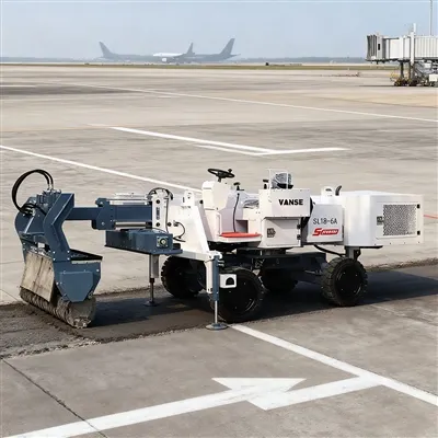
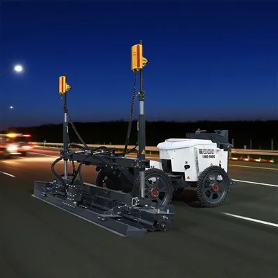
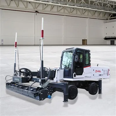
Detailed explanation of concrete laser leveling machine pouring leveling construction and leveling control matters

Detailed explanation of concrete laser leveling machine pouring leveling construction and leveling control matters
1. Preparation
1.1 After the base layer is processed, the equipment of the laser paver is debugged, and the fixed reference level point is drawn according to the original level point; the non-woven fabric is laid, the side formwork is supported, the laser transmitter is erected, and the ground level is introduced according to the original level point. Laser leveling machine.
1.2 Conveying concrete
Commercial concrete is used, and the commercial concrete is transported to the entrance and exit of the garage by tank truck, and then transported to the construction site by a three-wheel dump truck.
1.3 Standard calibration
Use a hand-held laser receiver to check the elevation of the floor, introduce the elevation into the laser paver, and adjust the reference point (±0.00) on the leveling machine.

2. Concrete paving
Pouring steps:
(1) After the formwork is supported, the warehouse should be cleaned one day in advance before pouring concrete, rinsed and soaked with water. When pouring is approaching, drain the open water and sweep the cement slurry or interface agent. At this time, no obvious water accumulation is strictly prohibited. If there is, it must be resolutely removed before paving concrete.
(2) After the concrete is put down, it should be preliminarily leveled, and the leveling height should be 3 cm thicker than the elevation. Then level it with a laser paver. The corners that cannot be leveled can be leveled with a gasoline leveler or manually.
(3) When the warehouse near the wall is being poured, after the leveling machine walks over, it must be scraped with a scraper in time. and so on.
(4) For areas where concrete mixer trucks cannot be driven to the site, tractors should be used to transfer concrete. After the pouring is completed, the floor finishing construction begins when the concrete is initially set.
(5) When the warehouse near the wall is being poured, it must be leveled with a scraper in time after the leveling machine has passed by. and so on.
(6) For areas where concrete mixer trucks cannot be driven to the site, tractors should be used to transfer concrete. After the pouring is completed, the floor finishing construction begins when the concrete is initially set.
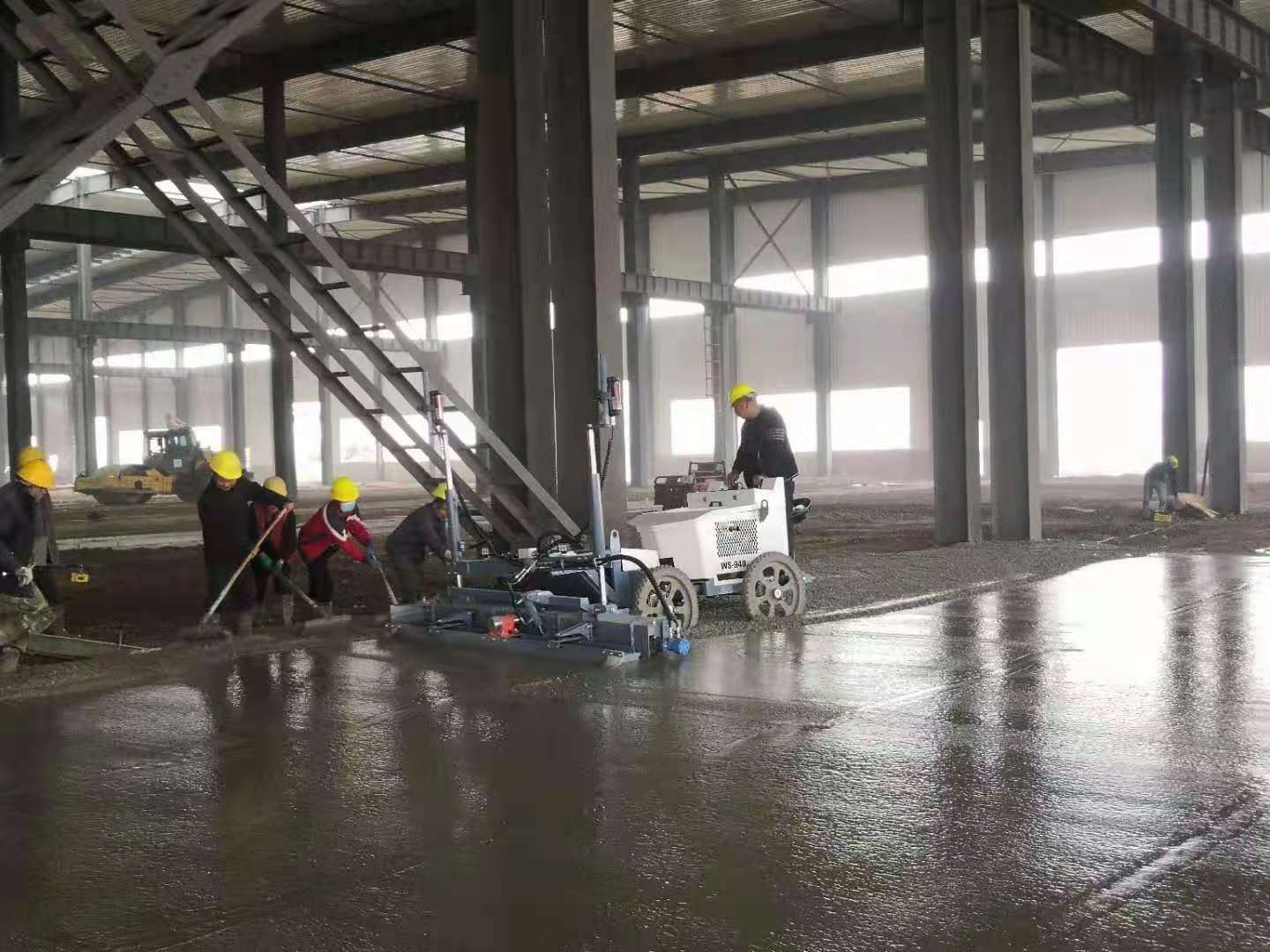
3. During construction, the laser signal received by the receiver of the laser paver (frequency of 10 times per second) automatically adjusts the elevation in real time to ensure that the construction elevation is always at the set standard. Because the laser transmitter is fixed after being set up, it can ensure that the construction of a large area of ground does not produce cumulative errors.
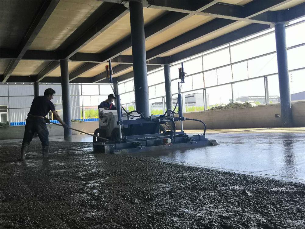
4. During the construction, the operator uses a hand-held laser receiver to detect the ground after the machine is constructed, and again ensures that the flatness error is within the controllable range.
If there is anything you don't understand, you can consult us, and we will continue to answer for you.
Thanks to All the Friends Who Support and Trust Shandong Vanse Machinery Technology Co., Ltd.
If you want to know more about Shandong Vanse Machinery Technology Co., Ltd. or have any questions, please feel free to contact us:
Our Factory
Shandong Vanse Machinery Technology Co., Ltd.








Share this article

About the Author: Shandong Vanse Machinery Technology Co., Ltd.
Shandong Vanse Machinery Technology Co., Ltd. is a high-tech manufacturer specializing in concrete construction machinery, including laser screeds and related equipment. The company integrates R&D, production, and global sales, with products exported to over 60 countries and widely used in infrastructure projects worldwide.
Previous Post
Next Post
Related Articles
You Might Also Like
Standards for Testing the Bond Strength between Dry-Spread Materials and Concrete Substrates
In anti-corrosion flooring construction, the bond strength between dry-spread materials (such as corundum and acid-resistant aggregates) and the concrete substrate directly determines whether the flooring will peel, flake, or allow anti-corrosion media to penetrate. For this type of "composite structure," the main testing standards and methods are as follows: Currently, the most directly recognized indicator in the industry is tensile strength. International Standard: ASTM D4541 (Standard Test Method for Pull-Off Strength of Coatings Using Portable Adhesion Testers) Domestic Standard: GB/T 5210 "Paints and Varnishes – Pull-Off Adhesion Test" or JGJ/T 70 "Basic Performance Test Methods for Building Mortar". Corrosion Protection Standard: GB 50212 "Code for Construction of Corrosion Protection Engineering for Buildings". Core Drilling/Kernel Cutting: Using a hollow drill bit, cut a ring, typically 50mm in diameter, into the hardened floor surface. The kerf depth should penetrate the dry-spread layer and reach the concrete base layer by approximately 5mm-10mm. Steel Ingot Adhesion: Adhere a standard steel ingot (Dolly) to the surface of the ring using high-strength epoxy resin adhesive. Pressure Pull-Out: Apply tension at a constant rate using a fully automatic or manual pull-out tester until the specimen detaches. Bond strength is not only determined by its numerical value (MPa), but also by the location of fracture, which is crucial for diagnosing construction quality: Location of failure Judgment Result Cause Analysis Concrete base layer failure Pass The adhesion strength is greater than the substrate strength, which is the ideal state. Bond interface failure Fail/Risk This indicates that the material was applied too late, and the aggregate did not enter the concrete hydration system. Dry-spread layer internal failure Requires Evaluation This indicates that the dry-applied material itself lacks strength or the surface was not properly smoothed. Adhesive layer failure Invalid Test The adhesive did not adhere well or the surface was not cleaned properly; retesting is required. Specifications: For high-performance anti-corrosion flooring, a tensile strength of ≥ 1.5 MPa is typically required. For environments subjected to heavy loads and strong chemical corrosion, a strength of ≥ 2.0 MPa is recommended. Besides direct pull-out testing, the following physical indicators indirectly reflect the bonding quality: GB/T 16925 (Indentation Hardness/Impact Test): Tests whether the dry-spread layer will delaminate and detach from the substrate under heavy impact. Hollow Zone Test (Tapping Method): According to GB 50209 "Code for Acceptance of Construction Quality of Building Ground Engineering", tap with a 0.5kg drumstick; there should be no hollow sound. Imperibility Test (ISAT): Measures the amount of water that permeates per unit time. If the bond is not dense, the permeability will be significantly increased. If you are preparing to outsource laboratory testing, it is recommended to reserve at least three representative test sites. Do you need to prepare inspection and certification documents, or is there a localized detachment at the construction site? If it's the latter, I can help you analyze the specific fracture surface characteristics to find the cause. Note: The parameters provided in this document are for reference only and are not mandatory. Due to differences in technical characteristics between different brands and models of laser levelers, please consult the manufacturer for a suitable solution before actual operation. This reference document assumes no responsibility for any issues arising from failure to follow the manufacturer's instructions.Key points for routine inspection, fault early warning and maintenance of the hydraulic system of concrete laser leveling
The routine inspection, fault early warning and maintenance points of the hydraulic system of the concrete laser leveling are a crucial topic, as the health condition of the hydraulic system directly determines the construction efficiency, leveling accuracy and equipment service life of the leveling. The following is a detailed and systematic guide. Objective: To prevent problems before they occur and promptly identify potential issues through daily observation. Oil level check: When the equipment is parked on a level ground and the hydraulic system is not started (or the cylinder has been retracted), check the oil level gauge in the hydraulic oil tank. The oil level should be between the marked upper and lower scale lines. Low oil level can cause the pump to run dry, the system to overheat and get damaged. If the oil level is too high, it may cause excessive pressure or oil leakage from the breather valve when the oil temperature rises. Leak inspection: Carefully inspect the entire hydraulic system, including: Pipe joints: Check for oil stains or dripping oil. Cylinder piston rod: Check for any scratches, bends or continuous leakage. Hydraulic pump, valve block, motor: Check if there is any leakage at the mating surface. Fuel tank surface: Whether it is clean and free of oil stains. Oil color: Observe the color of the hydraulic oil through the oil level gauge. New hydraulic oil is usually transparent amber in color. If it is found to be turbid and opaque (possibly water ingress), darker and blackened in color (possibly oxidation and deterioration), or milky white (definitely water ingress and emulsification), further treatment is required. Abnormal noise: Start the engine and operate various hydraulic actions (lifting, walking, vibration, etc.). Listen carefully for any sharp "click-click" sounds (cavitation sounds) or continuous dull abnormal noises from the hydraulic pump (possibly due to internal wear of the pump or motor). Vibration and Pulse: Touch the hydraulic pipeline with your hand to feel if there is any abnormally intense vibration or pulse sensation. This may be a sign of oil circuit blockage or pump/motor failure. Temperature: After working for a period of time, touch the outer shell of the hydraulic oil tank with your hand. If it feels hot to the touch (the temperature may exceed 60-70°C), it indicates that the system is overheated and needs to be shut down for inspection. Slow movement: Test the movement of all cylinders and motors to see if there is any slowdown in speed, weakness or jamming. Pressure maintenance: For the lifting cylinder, observe whether there is obvious "sinking" (i.e., internal leakage) after it is lifted. Objective: Identify early symptoms of faults to prevent minor issues from evolving into major ones. Warning signal Analysis of Possible causes Potential risk Slow and weak movements 1. Insufficient hydraulic oil or incorrect viscosity of the oil. The leveling accuracy has declined, making it impossible to work normally and resulting in low efficiency. 2. The main pump is worn out and internal leakage occurs, resulting in insufficient pressure/flow. 3. The set pressure of the relief valve (safety valve) is too low or the valve core is stuck. 4. Severe internal leakage of the actuator (cylinder/motor). Abnormal noise from the system (pump 1. The oil suction pipeline is clogged or the filter element is dirty. The hydraulic pump will be severely damaged in the short term and must be shut down immediately. 2. When the oil level is too low, the pump sucks air, causing cavitation. 3. Air mixed into the hydraulic oil (due to poor sealing of the pipelines). 4. The bearings or internal components of the pump itself are damaged. The system is severely overheating. 1. The hydraulic oil cooler is clogged (air-cooled or water-cooled). Accelerate the oxidation and deterioration of the oil, the aging of seals, and the wear of all hydraulic components. 2. The relief valve is frequently opened or the set pressure is too high. 3. Improper viscosity or deterioration of the hydraulic oil. 4. Severe leakage inside the pump or valve causes energy loss, which is converted into heat energy. The cylinder is crawling and shaking 1. There is air in the cylinder. It affects the stability of the leveling operation, causing waves to appear on the ground. 2. The wear of the piston seal in the oil cylinder leads to unstable pressure. 3. Oil contamination leads to the valve core of the control valve getting stuck and discontinuous movement. The hydraulic oil deteriorates rapidly 1. The oil temperature has been too high for a long time, leading to oxidation. Cause abrasive wear and corrosion of all hydraulic components. 2. Water enters the oil (such as leakage from the water cooler). 3. Contaminants (dust, metal shavings) invade the system. External leakage Aging of seals, damage to oil seals, loose joints, and wear and rupture of pipelines. Waste of oil, environmental pollution, insufficient system pressure, and even fire. Objective: Establish a scientific maintenance system to maximize the system's lifespan. Regularly change the hydraulic oil and filter elements: Strictly follow the oil change cycle specified by the equipment manufacturer (usually 500-1000 working hours). In harsh and dusty environments, the cycle should be shortened. When changing the oil, all hydraulic filter elements (suction oil filter, return oil filter, pressure oil filter) must be replaced simultaneously. Refueling must be filtered: When adding or replacing new oil, it is essential to use a dedicated fuel pump and filtering device. It is strictly forbidden to directly pour the oil drum into the fuel tank. Keep the fuel tank clean: Clean the area around the fuel tank cap before refueling to prevent debris from falling in. Regularly clean the magnetic plugs inside the fuel tank. Regularly clean the fins of the hydraulic oil radiator to ensure good ventilation and no blockage from concrete, dust, etc. Avoid the equipment operating under extremely high load for a long time. If the ambient temperature is high, an auxiliary cooler can be considered for installation. Ensure the sealing of all suction pipelines to prevent the pump from being sucked empty. Regularly check whether the fuel tank breathing valve is unobstructed. After the machine stops, regularly check the water outlet at the bottom of the fuel tank for any water. For key equipment, samples can be taken regularly and sent to professional laboratories for testing. The analysis report can inform you of the contamination degree of the oil, the composition of worn metals, water content and physical and chemical indicators, thereby accurately predicting faults, achieving oil replacement based on quality and saving costs. Avoid operating the hydraulic cylinder piston rod only when it reaches the end of its stroke. Instead, release the operating rod before approaching the end to take advantage of inertia to reach the position and reduce the impact. When starting up in winter, it should first run at low speed without load for a period of time to allow the oil temperature to rise and the viscosity to decrease before commencing operations. Maintain the project Daily/ Per shift Weekly/ 50 hours Month/ 250 hours Every six months / 1,000 hours Check the hydraulic oil level ✓ Check for leakage, abnormal noise and temperature ✓ Clean the surface of the fuel tank and radiator ✓ ✓ Check the tightness of the pipelines and joints ✓ Replace the hydraulic return oil filter element ✓ Take oil samples for testing (suggested) ✓ Completely replace the hydraulic oil and all filter elements ✓ (As per the manufacturer's regulations When it comes to the hydraulic system of the concrete laser leveling, the principle that "cleanliness is fundamental and prevention is key" must be adhered to. Only by conducting rigorous daily inspections to identify early warning signals and combining them with regular systematic maintenance can the stability and reliability of the equipment during the construction period be ensured, ultimately achieving high-precision and high-efficiency floor construction and significantly reducing the operating costs throughout the entire life cycle. Note: The parameters provided in this document are for reference only and are not mandatory. Due to differences in technical characteristics between different brands and models of laser levelers, please consult the manufacturer for a suitable solution before actual operation. This reference document assumes no responsibility for any issues arising from failure to follow the manufacturer's instructions.Quality testing method for concrete pavement
Concrete pavement occupies a vital position in modern transportation infrastructure, and its quality is directly related to the service life, driving safety and comfort of the road. In order to ensure the quality of concrete pavement, comprehensive and scientific quality inspection is indispensable. With the continuous advancement of science and technology, advanced equipment such as concrete laser leveling machine is increasingly widely used in concrete construction, which also puts forward higher requirements for quality inspection methods. The following will introduce the quality inspection method for concrete pavement in detail. As the key cementing material of concrete, the quality of cement has a profound impact on the performance of concrete. When testing cement, the following aspects should be paid attention to: Strength: According to relevant standards, the 3-day and 28-day compressive and flexural strength of cement is measured through cement mortar strength test to ensure that it meets the design requirements. For example, for 42.5-grade ordinary silicate cement commonly used in road engineering, the 28-day compressive strength should not be less than 42.5MPa. Set time: Use a setting time meter to detect the initial and final setting time of cement. Generally speaking, the initial setting time of ordinary Portland cement shall not be earlier than 45 minutes, and the final setting time shall not be later than 10 hours, so as to ensure that the concrete has sufficient operation time during the construction process and can harden in time. Stability: The boiling method is used to test the stability of cement to ensure that the volume change of cement during the hardening process is uniform, without abnormal phenomena such as cracking, so as to avoid quality problems such as cracks in the concrete pavement due to poor cement stability. Aggregates include coarse aggregates (such as crushed stone and pebbles) and fine aggregates (such as natural sand and machine-made sand). The key points of quality inspection are as follows: Particle grading: The particle grading of aggregates is determined by screening tests to ensure that it meets the requirements of relevant standards. Good particle grading can make the aggregates compactly stacked in concrete, reduce the amount of cement used, and improve the strength and durability of concrete. For example, the maximum particle size of coarse aggregates is usually no more than 1/3 of the thickness of the concrete slab, and should meet the requirements of continuous grading. Mud content and mud block content: Excessive mud and mud block content will reduce the bonding force between aggregate and cement paste, affecting the strength and durability of concrete. The mud and mud block content of aggregates are determined by the water washing method. Generally, the mud content of coarse aggregates is required to be no more than 1%, and the mud block content is no more than 0.5%; the mud content of fine aggregates is required to be no more than 3%, and the mud block content is no more than 1%. Robustness: The sodium sulfate solution immersion method is used to test the robustness of aggregates and evaluate their durability under the influence of climate and environmental changes. Aggregates with good robustness can effectively resist the erosion of external factors and extend the service life of concrete pavements. Admixtures can significantly improve the performance of concrete and need to be strictly tested before use: Water reduction rate: The water reduction rate is an important indicator for measuring the performance of water reducers. By comparing the water consumption of concrete mixtures with and without admixtures, the water reduction rate is calculated to ensure that it meets the requirements of the product manual. Generally, the water reduction rate of high-efficiency water reducers should not be less than 15%. Setting time difference: Detect the effect of admixtures on the setting time of concrete. The initial setting time difference and the final setting time difference should meet the construction requirements to avoid abnormal setting time of concrete due to admixtures, which will affect the construction progress and quality. Compressive strength ratio: Determine the compressive strength ratio of concrete with admixtures and benchmark concrete at different ages, evaluate the effect of admixtures on the strength development of concrete, and ensure that admixtures will not reduce the final strength of concrete. The water used for concrete mixing and curing should meet relevant standards and should not contain harmful substances that affect the performance of concrete. The test items include pH value, insoluble matter, soluble matter, chloride, sulfate, etc. For example, it is generally required that the pH value of water used for concrete is not less than 4, and the chloride content (measured in Cl⁻) does not exceed 500mg/L (reinforced concrete) or 1000mg/L (plain concrete). Slump is an important indicator for measuring the fluidity of concrete mixture. At the construction site, a slump cone is used for testing. The concrete mixture is loaded into the slump cone in three layers, and each layer is rammed 25 times. Then the slump cone is lifted vertically to measure the height difference between the cone height and the highest point of the concrete specimen after collapse, which is the slump value. According to the construction requirements, the appropriate slump can ensure the uniformity and density of the concrete during the paving process. For example, when concrete laser leveling machine is used for concrete paving, the slump is generally controlled at 30-50mm to ensure that the concrete can be paved smoothly and can achieve good flatness under the action of the laser leveling machine. For dry and hard concrete mixtures, a Vebe consistency meter is required to detect its Vebe consistency. This indicator reflects the consistency of the concrete mixture under vibration. During the test, the concrete mixture is loaded into the slump cone, and then the slump cone is placed in the container of the Vebe consistency meter. After lifting the slump cone, the vibration table is turned on and the stopwatch is started at the same time. When the concrete surface changes from uneven to flat, the stopwatch is stopped. The recorded time is the Vebe consistency value. The Vebe consistency value should meet the design and construction requirements. Generally, the Vebe consistency of dry hard concrete is between 10-30s. The air content has an important influence on the frost resistance and durability of concrete. The air content of the concrete mixture is tested using an air content meter. The appropriate amount of air content can form tiny bubbles inside the concrete, relieve the stress caused by the freeze-thaw cycle, and improve the frost resistance of the concrete. Generally, the air content of the concrete is required to be controlled between 3% and 5%, and the specific value is determined according to the environment and design requirements of the project. The temperature of the concrete mixture has a significant impact on its performance and construction quality. In a high temperature environment, if the temperature of the concrete mixture is too high, it will accelerate the cement hydration reaction, resulting in too fast slump loss and even false setting; in a low temperature environment, if the temperature of the concrete mixture is too low, it will delay the cement hydration reaction and affect the strength growth of the concrete. Use a thermometer to measure the temperature of the concrete mixture at the mixing site and the pouring site. According to the ambient temperature and construction requirements, take corresponding temperature control measures, such as cooling the raw materials in high temperatures in summer and heating and insulating the concrete in low temperatures in winter. Flatness: The flatness of the base directly affects the thickness uniformity and driving comfort of the concrete pavement. Use a 3m ruler or a flatness meter to detect the flatness of the base surface, and the allowable deviation is generally not more than 10mm. For parts that do not meet the flatness requirements, they should be trimmed to ensure that the base surface is flat, providing a good foundation for the construction of the concrete pavement. Compactness: Insufficient compaction of the base will cause road subsidence and other diseases. The compaction degree of the base layer is tested by sand filling method, water filling method or ring knife method to ensure that it meets the design requirements. For example, for lime-stabilized soil base layer, the compaction degree is generally required to be not less than 95%. Strength: The strength of the base layer is the key to ensuring the bearing capacity of the pavement structure. The strength of the base layer is tested by making specimens for unconfined compressive strength test through on-site core sampling. The strength of the base layer should meet the design requirements to ensure that it can withstand the vehicle load transmitted from the concrete pavement. Casting thickness: During the concrete pouring process, the pouring thickness of the concrete is regularly tested using a steel chisel or other measuring tools to ensure that it meets the design requirements. The thickness deviation of the concrete slab is generally controlled within the range of +10mm, -5mm. Insufficient thickness will affect the bearing capacity and service life of the pavement, while excessive thickness will cause material waste. Vibration quality: Vibration is a key link to ensure the compactness of concrete. The vibration effect can be judged by observing the surface condition of the concrete, such as whether there is slurry overflow and bubble discharge. At the same time, an inserted vibrator can be used to detect the density of the concrete inside to ensure uniform vibration without missing vibration or over-vibration. For concrete pavements constructed with a concrete laser leveling machine, it is necessary to ensure that the concrete has been initially vibrated and compacted before the laser leveling machine is operated to ensure that the laser leveling machine can play a better role and achieve high-precision flatness control. Rebar arrangement (if any): For reinforced concrete pavements, check whether the type, specification, quantity, spacing, position of the steel bars, and the connection method and anchorage length of the steel bars meet the design requirements. Improper steel bar arrangement will affect the structural performance of the concrete pavement, such as bearing capacity and crack resistance. At the construction site, a steel ruler is used to measure the spacing and position of the steel bars, observe the connection and anchorage of the steel bars, and ensure that the quality of the steel bar project meets the standards. 3m ruler method: This is a commonly used road surface flatness detection method. Place a 3m ruler along the longitudinal direction of the road surface and measure the maximum gap between the ruler and the road surface to assess the road surface flatness. Measure 2 locations every 200m, and measure 10 feet continuously at each location. Judge whether the road surface flatness meets the requirements based on the gap value. Generally, the allowable deviation is no more than 5mm. Continuous flatness meter method: This method can continuously measure the road surface flatness, with high detection efficiency and more accurate results. The continuous flatness meter travels along the road surface, collects the elevation data of the road surface through sensors, and calculates the flatness index (such as the International Roughness Index IRI). After the concrete pavement construction is completed, this method can be used to conduct a comprehensive inspection of the road surface to provide detailed data for road surface quality assessment. For roads constructed with concrete laser leveling machines, the continuous flatness meter test results can intuitively reflect the construction effect of the laser leveling machine. The IRI value should generally be controlled within a certain range, such as no more than 2.0m/km, to ensure that the road surface has good driving comfort. Vehicle-mounted bump accumulation meter method: The bumpiness of the road surface is measured by the bumpiness of the vehicle when it is driving on the road. The vertical vibration acceleration of the vehicle is measured by a sensor installed on the vehicle, and the bump accumulation value (VBI) is converted. This method has a fast detection speed and is suitable for rapid detection of large-area road surface flatness. When conducting quality inspection on concrete pavement, the road surface flatness condition can be evaluated according to the VBI value, and verified with other detection methods to fully grasp the road surface quality. Structural depth: The structural depth reflects the macro texture depth of the road surface and has an important impact on the road surface skid resistance. The road surface structural depth is detected by sand spreading method or laser structural depth meter. The sand spreading method is to spread a certain amount of standard sand on the road surface, flatten the sand into a circle with a push plate, measure the coverage area of the sand, and calculate the structural depth value. The laser structural depth meter uses laser scanning technology to quickly measure the road surface structural depth. Generally, the structural depth of cement concrete pavement is required to be between 0.7 and 1.1mm to ensure that the road surface still has sufficient skid resistance under adverse conditions such as moisture. Friction coefficient: The friction coefficient is a direct indicator of the road surface skid resistance. Use a pendulum friction meter or a dynamic friction coefficient tester to detect the road surface friction coefficient. The pendulum friction meter measures the friction force of the pendulum sliding on the road surface when it swings freely from a certain height, and calculates the friction coefficient of the road surface (BPN value). The dynamic friction coefficient tester simulates the friction between the tire and the road surface during vehicle driving and measures the friction coefficient in real time. According to different road grades and usage requirements, the road friction coefficient should reach the corresponding standard value. For example, the BPN value of general urban roads should not be less than 45 to ensure driving safety. Core drilling method: The core drilling method is the most direct and reliable method to detect the strength of concrete pavement. After the concrete pavement is hardened, a core drill is used to drill a core sample on the pavement. The diameter of the core sample is generally not less than 100mm and not less than 3 times the maximum particle size of the aggregate. After the core sample is processed into a standard test piece, a compressive strength test is carried out, and the strength of the concrete pavement is evaluated based on the test results. The core drilling position should be representative, and at least 1 core sample should be drilled every 3km for each lane. The compressive strength of the core sample should meet the design requirements. For example, for a concrete pavement with a design strength grade of C30, the average compressive strength of the core sample should not be less than 30MPa, and the minimum value should not be less than 25.5MPa. Rebound method: The rebound method is a non-destructive detection method. The rebound value of the concrete surface is detected by a rebound hammer. The strength of the concrete is estimated based on the correlation between the rebound value and the concrete strength. When using the rebound method, the measurement areas should be evenly arranged on the pavement. The area of each measurement area should not be greater than 0.04m², and the number of measurement areas should not be less than 10. At the same time, the influence of the carbonization depth of concrete on the rebound value should be considered and necessary corrections should be made. The detection results of the rebound method have certain limitations. It is generally used as an auxiliary detection method of the core drilling method for the preliminary evaluation of the strength of large-area concrete pavements. Ultrasonic rebound comprehensive method: This method combines the advantages of the ultrasonic method and the rebound method. By measuring the ultrasonic sound velocity and rebound value of concrete, the strength of concrete is comprehensively estimated. Ultrasonic sound velocity reflects the density and uniformity of concrete, and the rebound value reflects the hardness of concrete surface. The combination of the two can more accurately evaluate the strength of concrete. The ultrasonic rebound comprehensive method is suitable for batch testing of concrete pavement strength. The accuracy of the test results is relatively high, but the operation is relatively complex and requires professional testing equipment and technicians. Core drilling method: The drilled core sample can not only be used for strength testing, but also can intuitively measure the thickness of the concrete pavement. Use a caliper to measure the thickness of the core sample with an accuracy of 0.1mm. Drill sample cores at 2 locations on the left and right within every 100m of pavement paving width to test the thickness of the board. The pavement thickness deviation should meet the design requirements, and the general allowable deviation is +10mm, -5mm. Radar detection method: Use ground penetrating radar to emit high-frequency electromagnetic waves to the pavement, and detect the thickness of the concrete pavement based on the reflection characteristics of the electromagnetic waves at the interface of different media (such as concrete and base). The radar detection method has the advantages of fast, non-destructive, and continuous detection, and can obtain thickness data of large-area pavements in a short time. However, this method requires professional radar equipment and data analysis software, and the detection results are greatly affected by factors such as the material properties and water content of the pavement structure layer, and calibration and verification are required before use. Appearance inspection: Observe the surface of the concrete pavement with the naked eye to check whether there are cracks. Record the location, direction, length, width and other information of the cracks. For cracks with smaller width, a crack observation instrument can be used to measure and accurately measure the crack width. Generally, cracks with a width of no more than 0.2mm are considered to be small cracks and can be closed on the surface; cracks with a width of more than 0.2mm need to analyze the cause and take corresponding repair measures, such as grouting repair. Non-destructive testing technology: In addition to appearance inspection, non-destructive testing equipment such as ultrasonic flaw detectors and infrared thermal imagers can also be used to detect whether there are cracks inside the concrete pavement. The ultrasonic flaw detector transmits and receives ultrasonic waves, and judges whether there are defects and cracks inside according to the reflection and refraction characteristics of ultrasonic waves when propagating inside the concrete. The infrared thermal imager uses the difference in temperature distribution on the surface of the object to detect internal defects. When there are cracks inside the concrete, a corresponding temperature abnormality area will be formed on the surface, which can be intuitively displayed through infrared thermal images. Non-destructive testing technology can detect hidden cracks inside the pavement, provide a basis for timely prevention and control measures, and ensure the integrity and safety of the pavement structure.