Technical Knowledge
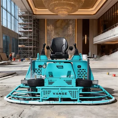
What large outdoor scenes are ride-on concrete power trowels suitable for?

1. Large Square
– Ground Features:
– Large squares have a large ground area and are usually paved with concrete or stone. For example, city center squares, commercial squares, etc., may range from several thousand square meters to tens of thousands of square meters. The thickness of the concrete square floor is generally around 10-20 cm, while the stone floor has different thicknesses and specifications.
– Construction Requirements:
– The ground flatness requirements are high, and it is necessary to ensure the comfort of pedestrians and the stable placement of activity facilities (such as sculptures, fountains, etc.). At the same time, the square floor may need a certain drainage slope to prevent water accumulation. With its high power and large trowel diameter, the driving trowel can quickly and effectively trowel large square floors, and the slope and glossiness of the ground can be controlled by adjusting the operating parameters of the trowel, so that the square floor can achieve the ideal construction effect.
2. Airport runways and aprons
– Ground Features:
– The ground of airport runways and aprons is a thick layer of high-strength concrete structure. The runway length can reach several thousand meters and the width is tens of meters. The apron area is also quite large. The thickness of runway concrete is generally around 30-50 cm, and it needs to withstand the huge impact force when the aircraft takes off and lands.
– Construction requirements:
– There are extremely strict standards for ground flatness and roughness. The driving trowel can accurately control the troweling process to ensure that the flatness error of the runway and apron is within a very small range (for example, the longitudinal flatness error of the runway does not exceed 3-5 mm), and can set different roughness according to different areas (such as runways, connecting roads, aprons, etc.) to meet the safety requirements of aircraft take-off and landing and taxiing. Its efficient working performance can also complete large-scale airport ground construction in a short time, reducing the impact on airport operations.
3. Large parking lot
– Ground characteristics:
– Large parking lots have a large ground area and are generally concrete structures. The ground may have a certain slope design for drainage and vehicle driving guidance. The parking lot ground also needs to be divided into parking spaces and passages.
– Construction requirements:
– The driving trowel can smooth the ground according to the design requirements of the parking lot on the basis of ensuring construction efficiency. For example, during the polishing process, the operation can be carried out according to the drainage slope requirements, and at the same time, the ground of the parking space and the passage has appropriate flatness and friction, which is convenient for the parking and entry and exit of vehicles. Moreover, the driving trowel can quickly complete the polishing work of a large area of parking lots and shorten the construction period.
4. Roads and sites in industrial parks
– Ground characteristics:
– The ground area of roads and sites in industrial parks is large, and the materials are mostly concrete. The roads need to meet the requirements of vehicle transportation (including heavy trucks), and the sites are used for placing equipment and stacking goods.
– Construction requirements:
– The driving trowel can provide efficient polishing services for the ground of industrial parks. For the road ground, it can make the road surface flat and enhance the bearing capacity and durability of the road. For the site ground, it can ensure that the goods are stacked stably and the equipment installation foundation is good. It has high working efficiency and is suitable for large-scale industrial park ground construction, which can effectively reduce labor costs and construction time.
Thanks to All the Friends Who Support and Trust Shandong Vanse Machinery Technology Co., Ltd.
If you want to know more about Shandong Vanse Machinery Technology Co., Ltd. or have any questions, please feel free to contact us:
Our Factory
Shandong Vanse Machinery Technology Co., Ltd.








Share this article

About the Author: Shandong Vanse Machinery Technology Co., Ltd.
Shandong Vanse Machinery Technology Co., Ltd. is a high-tech manufacturer specializing in concrete construction machinery, including laser screeds and related equipment. The company integrates R&D, production, and global sales, with products exported to over 60 countries and widely used in infrastructure projects worldwide.
Previous Post
Next Post
Related Articles
You Might Also Like
What are the common faults and troubleshooting methods of concrete laser leveling machines?
The concrete laser leveler is a high-tech equipment used for concrete construction. It uses laser technology to level the concrete surface to improve construction quality and efficiency. However, during use, the concrete laser leveling may experience some common faults, which can be repaired with some simple troubleshooting methods. The following will introduce common faults and troubleshooting methods of concrete laser leveling machines. 1. The device cannot be turned on. The device cannot be turned on because the power cord is not connected correctly, the battery is low, or the device itself is faulty. To troubleshoot this problem, you can check whether the power cord is connected correctly, whether the battery is charged or replaced with a new one, and whether there are other malfunctions in the device. 2. The device cannot receive signals. The failure of the device to receive signals may be caused by the GPS antenna being blocked, signal receiver failure, or surrounding signal interference. To troubleshoot this fault, you can check whether the GPS antenna is blocked or move to a better location, check whether the signal receiver is faulty or replace it with a new one, eliminate surrounding signal interference, etc. 3. The device cannot scan. The device cannot scan. The reason may be that the laser head is blocked, the laser head is faulty, or the control circuit is faulty. To troubleshoot this fault, you can check whether the laser head is blocked or clean, check whether the laser head is faulty or replace it with a new one, check whether the control circuit is faulty or repair the circuit, etc. 4. The device cannot transmit data. The device cannot transmit data. The reason may be that the memory card is full, the memory card is faulty, or the connection between the device and the computer is poor. To troubleshoot this problem, you can check whether the memory card is full or delete unnecessary files, check whether the memory card is faulty or replace it with a new one, check whether the connection between the device and the computer is good, etc. 5. The device cannot be calibrated. The failure of the device to be calibrated may be caused by incorrect calibration steps, incorrect placement of the device, or errors during the calibration process. To troubleshoot this problem, you can follow the correct calibration steps, place the device in the correct location, check if there are any errors during the calibration process, etc. 6. The equipment cannot perform automatic leveling. The failure of the equipment to perform automatic leveling may be caused by sensor failure, poor connection between the sensor and the equipment, or incorrect sensor position. To eliminate this fault, you can check whether the sensor is faulty or replace it with a new one, check whether the connection between the sensor and the device is good, adjust the position of the sensor, etc. 7. The equipment cannot perform automatic smoothing. The equipment cannot perform automatic smoothing. It may be caused by motor failure, poor connection between the smoother and the equipment, or incorrect position of the smoother. To eliminate this fault, you can check whether the motor is faulty or replace it with a new one, check whether the connection between the trowel and the equipment is good, adjust the position of the trowel, etc. 8. The equipment cannot perform automatic control. The failure of the equipment to perform automatic control may be caused by controller failure, control circuit failure or control program error. To eliminate this fault, you can check whether the controller is faulty or replace it with a new controller, check whether the control circuit is faulty or repair the circuit, check whether the control program is wrong or update the program, etc. In short, there are many common faults and troubleshooting methods for concrete laser leveling machines. When a fault occurs, you should first understand the basic operating methods of the machine, and then analyze and troubleshoot according to the actual situation. If you cannot solve the problem by yourself, it is recommended to seek help from professional technicians in time.Emergency handling and repair procedures for a power trowel after being soaked in water
Soaking a power trowel in water is a serious accident, but proper emergency handling can save the equipment to the greatest extent and prevent secondary damage. Please be sure to follow the following "Golden 24 Hours" emergency handling and repair procedures. Core principles: Power off, drainage, cleaning, and drying. Speed comes first! The most crucial step! Under no circumstances should you attempt to start the engine or connect the power supply (if it is an electric power trowel). Starting with water will directly lead to short circuits in the circuit and motor burnout, causing irreversible damage and extremely high maintenance costs. Engine/electric power trowel: Immediately turn off the ignition switch and remove the key. For the electric model, unplug the battery connection wire (pay attention to insulation). Battery: Disconnect the battery connection wires. First, remove the negative terminal, then the positive terminal. Posture adjustment: Tilt the power trowel to allow as much water inside the gearbox, engine air intake, radiator and other parts to flow out as possible. External cleaning: Use low-pressure clean water to quickly rinse off the mud and dirt on the machine surface to prevent lumps that are difficult to clean after drying. Note: Avoid directly flushing electrical components, bearing seals and other parts with high-pressure water guns. Remove the base/disc of the power trowel: This is the part where sand and mud are most likely to accumulate. Check the air filter: Immediately remove the air filter and check if water has entered. If water gets in, it must be replaced! Under no circumstances should it be used after being dried. Otherwise, sand and dust will enter the engine and cause cylinder pulling. Check the engine oil: Pull out the oil dipstick and check if the oil has turned white (milky white). This is a clear sign that water has entered the engine oil. If water gets in, it must be replaced immediately. Physical drying: Use a clean lint-free cloth or towel to dry all visible moisture, especially around the circuit interfaces, sensors, and spark plugs. Use compressed air (the pressure should not be too high) to dry all hard-to-reach areas such as crevices, circuit joints, engine heat sinks, and gearbox vent holes. You can also use the cold setting of a hair dryer to dry it. Natural ventilation: Place the equipment in a dry and well-ventilated area, open all openable covers (such as the engine hood), and let it air dry naturally. It is strictly prohibited to directly bake with hot air or open flame, as this will damage the circuits and seals. Core principle: Systematic inspection, from the outside in, and handling by modules. Spark plug: Remove the spark plug, check the electrode condition and dry it. You can pull the starter in the air several times to drain any possible accumulated water in the cylinder. Fuel system Fuel tank: Drain all fuel. Even if it seems that no water has entered, condensate water may still be present. Carburetor: Remove the carburetor and perform a thorough cleaning. Water will sink to the bottom of the carburetor, causing it to fail to start or operate unstably. This is a very crucial step. Engine oil: Regardless of the previous inspection results, new engine oil and oil filter must be replaced at this time. Ensure the purity of the oil circuit system. Ignition system and wiring harness: Check all wire joints and high-voltage packs for signs of corrosion or oxidation, and clean and dry them. Gearbox Check the lubricating oil of the gearbox. If water enters (the oil will become cloudy and milky white), it must be completely drained. Clean the interior of the gearbox with diesel or a special cleaning agent to remove moisture and impurities. Refill with brand new gear oil that meets the specifications. Bearings: The grease in the bearings of the main shaft, traveling wheels and other parts will fail if water gets into them. Although it may still be able to rotate in the short term, its lifespan has been severely damaged. It is strongly recommended to remove and replace all the main bearings and add new grease. Clutch and throttle cable: Check for rust or jamming, and add special lubricating oil to maintain its flexibility. Motor: If water has entered the interior of the motor, it must be opened by professional maintenance personnel for cleaning, drying and re-impregnation with insulating varnish; otherwise, it is very likely to burn out. Do not handle it by yourself! Switches and controllers: Carefully inspect all electrical components to ensure they are completely dry and free from corrosion. If you have any doubts, it is recommended to replace it. Cable: Check whether the insulation layer of the cable is damaged. Reassembly: Reinstall all the cleaned, dried and replaced components in sequence. Pre-startup inspection: Reconfirm that the fuel, engine oil and gear oil have been filled in place and all connecting parts have been tightened. Start the engine/motor under no-load conditions and observe whether it runs smoothly and if there are any abnormal noises. Then slowly increase the throttle and check whether the clutch and transmission system are working properly. Finally, conduct a short trial run on the leveled waste mortar or land to check if the smoothing function is normal. If handled promptly and correctly: It may only cost the expenses of replacing the air filter, engine oil, gear oil, spark plugs and cleaning the carburetor (several hundred yuan), and the equipment can return to normal. If not handled properly or delayed, it may lead to serious consequences such as engine cylinder pulling, connecting rod bending, motor burnout, bearing seizing, gear damage, etc. The maintenance cost may be as high as several thousand yuan, and even result in the direct scrapping of the equipment. Finally, it is recommended that if you are not familiar with the internal structure or if the equipment still fails to work properly after following the above steps, please immediately send it to a professional maintenance service station. Explain to the maintenance technician that the equipment has been soaked in water so that they can carry out targeted inspections. Time is money. Correct emergency handling can win precious opportunities for subsequent repairs! Note: The parameters provided in this document are for reference only and are not mandatory. Due to differences in technical characteristics between different brands and models of laser levelers, please consult the manufacturer for a suitable solution before actual operation. This reference document assumes no responsibility for any issues arising from failure to follow the manufacturer's instructions.How does a concrete laser leveling improve the flatness?
Concrete laser levelings improve flatness by: 1. Utilize laser technology to ensure the flatness and thickness of the concrete surface by precisely controlling the position and height of the laser beam. 2. Automated control technology can realize continuous and automatic leveling operations and improve work efficiency. 3. When performing automatic leveling, there is an accurate reference plane. Generally, when the main focus is to control the height, the tightrope method is suitable; when the main focus is to control the thickness, the floating datum beam method is adopted. Generally, tightrope is used for the bottom layer, and the floating datum beam method is used for the middle layer and surface layer. 4. The leveling machine has a vibration function, which can effectively compact the concrete materials evenly to the required thickness, further improving the flatness. 5. Leveling machines are usually equipped with high-precision sensors and controllers that can monitor and adjust the flatness and height of the concrete surface in real time. Therefore, through the above methods, the concrete laser leveling can effectively improve the flatness of the concrete surface, thereby improving the quality of stinging.