Technical Knowledge
Technical tips for leveling the power trowel chassis and calibrating the blade height consistency
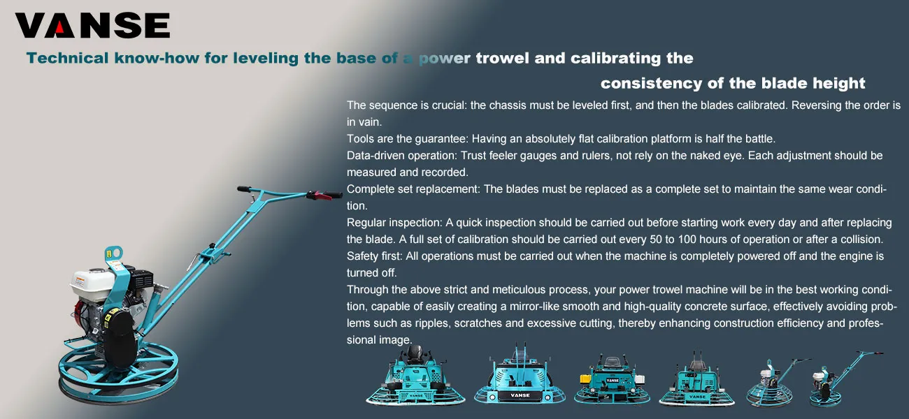
The construction quality of a power trowel (also known as a finishing machine) is 70% about leveling and 30% about operation. The flatness of the chassis and the blade is the key to determining whether the concrete surface ultimately achieves a mirror-like smoothness, without ripples or flaws.
The following are detailed technical tips for leveling the base of a power trowel and calibrating the consistency of the blade height, combining the experience of experienced masters with scientific methods.
Core principles: One benchmark, three unifications
One benchmark: Take the chassis as the sole benchmark. All blade adjustments must be based on a already leveled chassis.
Three unifications: uniform blade height, uniform inclination Angle, and uniform wear degree.
Part One: Chassis Leveling – Building a Solid Foundation
The chassis serves as the installation platform for the blade. If the chassis itself is uneven, the consistency of the blade is out of the question.
Calibration tool
First choice: A large and flat platform (such as a calibrated granite platform, a thick tempered glass tabletop or a new thick steel plate).
Second choice: On a very flat ground, use a known uniform thickness pad (such as a feeler gauge).
Essential items: feeler gauge, tape measure, marker pen.
Leveling steps (" platform method ") :
Cleaning and preparation
Thoroughly clean the chassis and remove all cement slurry and hard lumps. Check the chassis for any obvious deformation caused by the collision. If there is severe deformation, it needs to be corrected or replaced first.
Place the power trowel on the platform and ensure that the contact surface between the chassis and the platform is clean and free of debris.
Preliminary "Four-point measurement Method"
Consider the chassis as a clock face and measure the gap between the edge of the chassis and the surface of the platform at the four positions of 12 o 'clock, 3 o 'clock, 6 o 'clock and 9 o 'clock.
Use a feeler gauge to measure and record the gap values at four points.
Preliminary judgment: If the gap values at the four points differ by more than 1-2 millimeters, it indicates that the chassis is uneven and needs to be adjusted.
Adjust the pull rod (key step) :
The chassis of most power trowels is connected to the main unit through three or four adjustable pull rods.
Identify the high and low points: Based on the measurement data, determine which corner has the smallest clearance (the highest point of the chassis) and which has the largest clearance (the lowest point of the chassis).
Adjustment principle
To raise a certain Angle, loosen (counterclockwise) the lock nut of the pull rod corresponding to that Angle, then shorten the length of the pull rod (turn the pull rod body clockwise), and finally tighten the lock nut.
To lower a certain Angle, loosen the lock nut, then extend the length of the pull rod (turn it counterclockwise), and finally lock it.
The mnemonic: "High pines are short, low pines are long." (For the angles that need to be adjusted
Fine-tuning and review
After each adjustment, gently rotate the chassis (to prevent scratching the platform) and conduct the four-point measurement again.
Repeat steps 3 and 4 until the difference in gap values among the four points is controlled within 1 millimeter. At this point, it can be considered that the chassis has been leveled.
Part Two: Blade High Consistency Calibration – Achieving Precise Cutting
The calibration of the blade can only be carried out on the basis of ensuring that the chassis is absolutely flat.
Calibration tool
A ruler (preferably a high-precision steel ruler) or a dedicated blade height gauge.
Tape measure, marker pen, wrench.
Calibration steps (" rotational measurement method ") :
Installation and cleaning
Install a set of blades of consistent newness and oldness onto the blade seat. It is strictly prohibited to mix new and old blades!
Make sure that all the blade fixing bolts and blade seats are clean, the threads are undamaged and can be tightened in place.
Establish measurement benchmarks
Place the power trowel with the chassis adjusted on a flat ground.
Place a fixed reference point (such as a thin gasket or directly using the joints of floor tiles) on the ground beneath the chassis and within the rotation trajectory of the blade.
Stand a ruler vertically beside the reference point and measure the distance from one of the knife tips to the ground, recording it as the reference height H.
Rotational measurement, piece-by-piece comparison
It is extremely important: Manually and slowly rotate the base of the trotter so that the same position of the next blade (for example, the outermost end of both blades) rotates directly above the reference point.
Measure the distance from the tip of the knife to the ground again with a ruler.
Compare it with the reference height H and record the difference. For example: Blade 1 is H, blade 2 is H-1.5mm, and Blade 3 is H+1.0mm.
Measure all the blades in sequence.
Fine-tune the blade inclination Angle (core tip) :
The height of the blade is adjusted by the regulating bolt on the blade seat to change its inclination Angle.
Adjustment principle
If the measured value of a certain blade is low, it needs to be raised. The method is: tighten the adjusting bolt below the blade seat, or loosen the adjusting bolt above to lift the leading edge of the blade (the side close to the rotation direction).
If the measured value of a certain blade is too high, it needs to be reduced. The method is: Loosen the adjusting bolt below the blade seat or tighten the adjusting bolt above it to lower the leading edge of the blade.
Mnemonic: "High tight, low loose, the leading edge as the standard." (For the leading edge of the blade that needs to be adjusted
Cyclic calibration and final confirmation
After adjusting each blade, it is necessary to rotate and measure once again, as adjusting one blade may slightly affect the height of adjacent blades.
Repeat steps 3 and 4 until the difference between the measured height of all blades at the reference point and the reference height H is controlled within ±1 millimeter.
Final inspection: Rotate the chassis quickly and listen to the sound with your ears. When the highly uniform blades are idling, the wind sound is a uniform "buzz". Inconsistent ones will have a periodic noise of "puff puff".
Summary: Technical know-how and best practices
The sequence is crucial: the chassis must be leveled first, and then the blades calibrated. Reversing the order is in vain.
Tools are the guarantee: Having an absolutely flat calibration platform is half the battle.
Data-driven operation: Trust feeler gauges and rulers, not rely on the naked eye. Each adjustment should be measured and recorded.
Complete set replacement: The blades must be replaced as a complete set to maintain the same wear condition.
Regular inspection: A quick inspection should be carried out before starting work every day and after replacing the blade. A full set of calibration should be carried out every 50 to 100 hours of operation or after a collision.
Safety first: All operations must be carried out when the machine is completely powered off and the engine is turned off.
Through the above strict and meticulous process, your power trowel machine will be in the best working condition, capable of easily creating a mirror-like smooth and high-quality concrete surface, effectively avoiding problems such as ripples, scratches and excessive cutting, thereby enhancing construction efficiency and professional image.
Note: The parameters provided in this document are for reference only and are not mandatory. Due to differences in technical characteristics between different brands and models of laser levelers, please consult the manufacturer for a suitable solution before actual operation. This reference document assumes no responsibility for any issues arising from failure to follow the manufacturer's instructions.
Thanks to All the Friends Who Support and Trust Shandong Vanse Machinery Technology Co., Ltd.
If you want to know more about Shandong Vanse Machinery Technology Co., Ltd. or have any questions, please feel free to contact us:
Our Factory
Shandong Vanse Machinery Technology Co., Ltd.








Share this article

About the Author: Shandong Vanse Machinery Technology Co., Ltd.
Shandong Vanse Machinery Technology Co., Ltd. is a high-tech manufacturer specializing in concrete construction machinery, including laser screeds and related equipment. The company integrates R&D, production, and global sales, with products exported to over 60 countries and widely used in infrastructure projects worldwide.
Previous Post
Next Post
Related Articles
You Might Also Like
How does the concrete power trowel work? Please for example
The working principle of the concrete trowel mainly involves the mechanical structure and working power of the machine. First, a concrete trowel is a machine driven by an electric motor or a fuel engine. When the machine is started, the motor or engine drives the reducer to transmit power to the trowel plate. A trowel is a rotating flat plate equipped with a grinding wheel. The grinding wheel is usually made of high-hardness abrasives or diamonds and can polish cement floors. Secondly, when the trowel moves flatly, it smoothes and polishes the cement floor. This is because the rotation and pressure of the trowel plate causes the grinding wheel to rub against the concrete floor, thereby grinding and polishing the floor. Through the adjustment device, the movement speed and angle of the trowel plate can be adjusted to meet different construction needs. In addition, the concrete trowel can also achieve different levels of floor polishing and smoothing by replacing different polishing heads. Different polishing heads can adapt to different concrete strength, texture and surface quality requirements. To sum up, the working principle of the concrete troweling machine is to use a motor or engine to drive the reducer and transmit the power to the troweling plate, so that the troweling plate can scrape and smooth the cement floor during planar motion. At the same time, the movement speed and angle of the trowel plate can be adjusted through the adjustment device to meet different construction needs.How to choose the power trowel with appropriate power according to the construction scenario?
– The construction area of this type of scene is usually small, generally between tens of square meters and hundreds of square meters. For example, the floor area of the living room and bedroom of an ordinary residence may be around 20-50 square meters. The space is relatively narrow and there are many corners. – For this situation, a hand-held trowel with lower power is more suitable, with a power range of about 1-3kW. Because the low-power trowel has a small body and flexible operation, it can be easily moved in a limited space to perform trowel operations on narrow areas such as corners and walls. – Common indoor floor materials include cement mortar floors, fine stone concrete floors, etc. The thickness of these floor materials is relatively thin, generally within a few centimeters. – The precision requirements are high, and the trowel machine needs to be able to finely process the floor to achieve a high degree of flatness and glossiness. The speed and trowel force of the low-power trowel machine are relatively moderate, which can just meet this demand and avoid damaging the surface structure of the floor material due to excessive power. – The construction area is between a few hundred square meters and thousands of square meters, and the space is relatively open. For example, the area of a medium-sized warehouse may be 500-2000 square meters. – You can choose a moderately powered walk-behind or ride-on trowel. The power of a walk-behind trowel is generally 3-5kW, and the power of a ride-on trowel is 4-7kW. Ride-on trowels are more efficient when constructing large areas, and can quickly smooth the ground, saving time. Walk-behind trowels can be used in some corners that are difficult for ride-on trowels to reach. – The ground material may be thick concrete, about 10-20 cm thick. In this case, the trowel needs to have enough power to compact and smooth the ground. – Although the precision requirements are not as high as those for small indoor scenes, it is still necessary to ensure that the ground has a certain degree of flatness and smoothness to meet the needs of cargo storage or equipment installation. Medium-power trowels can complete the troweling task well while ensuring efficiency. – The construction area is very large, often exceeding thousands of square meters, or even tens of thousands of square meters. For example, a large city square may be 10,000 to 50,000 square meters in area, and an airport runway is even larger. – For this scenario, a high-power driving trowel should be selected, with a power of usually 7 to 15kW. Because large outdoor projects require a large amount of ground troweling work to be completed in a short period of time, a high-power trowel can provide sufficient power and high work efficiency to quickly cover a large area of the ground. – The ground material is generally a thick layer of high-strength concrete, which may be about 20 to 50 cm thick. The trowel needs to have strong power to handle this thick and hard ground material. – For precision requirements, large squares require good flatness and drainage slope of the ground, while airport runways have strict specifications for indicators such as flatness and roughness of the ground. High-power trowel machines can precisely control the trowel effect by adjusting components such as the trowel blade to meet these high standards.Shandong VANSE Concrete Laser Leveling Construction Plan (Brief Description)
Shandong VANSE Machinery Technology Co., Ltd.'s concrete laser leveling construction plan involves a series of detailed contents from project overview, construction methods, personnel configuration, machine equipment configuration to construction site material configuration. The following is a summary of key information: Project Overview – A large laser leveling machine is used on the first floor, and a small laser leveling machine is used upstairs and in the basement due to space limitations. – The laser leveling machine working diagram shows the application of the equipment in different environments. Construction Method – The construction process follows the ISO quality management procedure, including site closure management, area division, concrete pouring, leveling, wear-resistant floor construction, maintenance, and seam cutting. – Large-scale continuous construction reduces compartment seams, improves the integrity of the ground, and reduces subsequent maintenance costs. – Laser leveling technology achieves high levelness (FL≥15) and flatness (FF≥20) through laser transmitters and leveling machines, ensuring high-precision leveling of concrete. – The use of steel fiber concrete optimizes the crack resistance and foundation strength of concrete, and improves the compression, wear resistance and fatigue resistance of the floor. – Recommended steel fiber selection: length 35mm, diameter 0.75mm, aspect ratio 45, tensile strength ≥1100MPa, dosage 15-20kg/m³. Staffing plan – The configuration of various staff such as project managers, team leaders, concrete workers, laser leveling machine operators, etc. is planned, and it is emphasized that the project manager needs to arrive at the site in advance. Machine equipment configuration plan – The number and use of equipment such as large laser leveling machines, vibrators, double-head trowels, etc. are listed to ensure that the equipment is increased or decreased in time according to the conditions of the construction site. Construction site handover and material configuration plan – Includes specific construction methods such as template installation, concrete pouring, and leveling. – The armored seam system is used to disperse stress and improve the integrity and life of the ground. – Steel fiber concrete is used for secondary construction to improve crack resistance. – The laser leveling construction process includes equipment commissioning, concrete transportation, marking and verification, concrete paving, manual leveling, manual edge finishing and other steps. Parameters after laser floor construction is completed – Wear resistance ≤ 0.25g/cm², compressive strength ≥ 80MPa, flexural strength 11.5MPa, tensile strength 3.8MPa, Mohs hardness 7.5-8H, anti-slip property is the same as general cement floor. Wear-resistant hardened floor construction – The amount of wear-resistant aggregate spread is controlled at 4-5kg/㎡, and the construction process includes slurry rubbing, spreading wear-resistant materials, leveling, finishing, etc. Precautions and maintenance – Avoid pollution and damage to the ground in the later stage of construction, cover it with liquid maintenance film, keep it moist, and prohibit heavy objects from moving within 7 days. – Cut and fill the joints after two weeks of floor maintenance, and use polyurethane glue to fill the joints to ensure density. The above summary covers the main contents of the construction plan, including construction technical details, personnel and equipment configuration, material use and subsequent maintenance measures.