Technical Knowledge
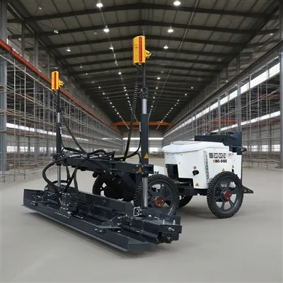
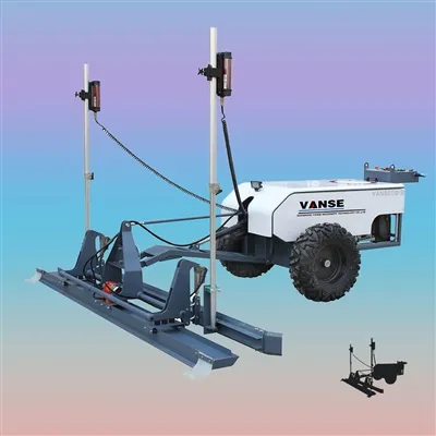
How does a concrete laser leveling improve the flatness?
Concrete laser levelings improve flatness by:
1. Utilize laser technology to ensure the flatness and thickness of the concrete surface by precisely controlling the position and height of the laser beam.
2. Automated control technology can realize continuous and automatic leveling operations and improve work efficiency.
3. When performing automatic leveling, there is an accurate reference plane. Generally, when the main focus is to control the height, the tightrope method is suitable; when the main focus is to control the thickness, the floating datum beam method is adopted. Generally, tightrope is used for the bottom layer, and the floating datum beam method is used for the middle layer and surface layer.
4. The leveling machine has a vibration function, which can effectively compact the concrete materials evenly to the required thickness, further improving the flatness.
5. Leveling machines are usually equipped with high-precision sensors and controllers that can monitor and adjust the flatness and height of the concrete surface in real time.
Therefore, through the above methods, the concrete laser leveling can effectively improve the flatness of the concrete surface, thereby improving the quality of stinging.


Thanks to All the Friends Who Support and Trust Shandong Vanse Machinery Technology Co., Ltd.
If you want to know more about Shandong Vanse Machinery Technology Co., Ltd. or have any questions, please feel free to contact us:
Our Factory
Shandong Vanse Machinery Technology Co., Ltd.








Share this article

About the Author: Shandong Vanse Machinery Technology Co., Ltd.
Shandong Vanse Machinery Technology Co., Ltd. is a high-tech manufacturer specializing in concrete construction machinery, including laser screeds and related equipment. The company integrates R&D, production, and global sales, with products exported to over 60 countries and widely used in infrastructure projects worldwide.
Previous Post
Next Post
Related Articles
You Might Also Like
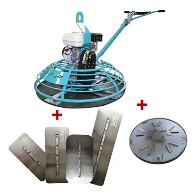
Does the operating skills of power trowel machine have a big impact on the trowel effect?
– Correct starting position: When starting the trowel, it is important to place it in an area where the concrete surface is flat and has been preliminarily processed (such as vibrated and scraped). If it is started in an uneven place or with debris, the trowel will be subject to uneven resistance at the beginning, which may cause the trowel blade to jump, thereby affecting the trowel effect. For example, on the newly poured concrete floor, if there are protruding stones or uncompacted parts, after starting the trowel, the trowel blade is likely to vibrate here, causing wavy patterns on the surrounding ground. – Stable starting speed: Starting the trowel smoothly can avoid the trowel blade suddenly accelerating and causing impact on the ground. For electric trowels, avoid quickly connecting the power supply to cause the motor to run at a high speed instantly; for gasoline trowels, when starting, you should follow the operating procedures and slowly pull the starting rope to allow the engine to gradually reach the working speed. If the starting speed is too fast, the impact force between the trowel and the ground is too large, which may leave scratches on the ground or cause partial peeling of the mortar layer on the concrete surface. – Travel speed control: The travel speed of the trowel directly affects the quality and efficiency of the trowel. If the speed is too fast, the trowel will stay in each area for too short a time, and the concrete surface cannot be fully compacted and smoothed, which can easily cause the ground to be rough and uneven. If the speed is too slow, although the trowel effect can be more refined, it will reduce work efficiency. For example, when troweling a large area of industrial plant floor, it is generally more appropriate to keep the travel speed at 3-5 meters per minute, which can not only ensure the quality of troweling, but also improve work efficiency to a certain extent. – Travel track planning: A reasonable travel track can make the trowel effect more uniform. Usually, a zigzag, circular or spiral travel track is used. The zigzag track is suitable for narrow and long areas, so that the trowel can fully cover every corner; the circular and spiral tracks are suitable for large circular or square areas, which can ensure that the trowel can evenly trowel from the center to the periphery or from the periphery to the center. If the walking track is chaotic, such as turning randomly or repeatedly over-troweling in certain areas, it will cause uneven troweling of the ground, high and low differences or local over-troweling. – Adjust pressure according to stage: Different pressures need to be applied at different stages during the troweling process. In the rough grinding stage after the initial setting of concrete, a larger pressure can be appropriately applied to compact the concrete surface and eliminate bubbles and pores. In the fine grinding stage, the pressure should be reduced so that the trowel slides gently on the ground, mainly used to improve the finish of the ground. For example, during rough grinding, the hand-held trowel can increase the pressure by pressing the operating handle appropriately; during fine grinding, the handle is relaxed to let the trowel contact the ground naturally. If the pressure is not properly controlled, excessive pressure during the fine grinding stage may damage the ground that has been initially leveled, resulting in new scratches and unevenness. – Importance of even pressure: Ensure that pressure is evenly distributed on the trowel blade, whether in the rough or fine grinding stage. Uneven pressure can cause some parts of the trowel blade to exert too much force on the ground, while other parts exert insufficient force, resulting in local unevenness and inconsistent gloss on the ground. Operators need to achieve even pressure through skilled operation and good control of the trowel. – Special tools or techniques for corners: For areas such as corners and edges that are difficult for the trowel to cover directly, operating skills are particularly critical. You can use a small handheld trowel or a special corner trowel tool for processing. When using a handheld trowel, keep it perpendicular to the corner or edge and rotate it slowly with a small radius to ensure that the concrete in the corner can be fully compacted and smoothed. Without the correct corner treatment skills, these areas can easily be overlooked, resulting in uneven and rough corners, affecting the finishing quality of the entire floor.The Concrete Laser Leveling Equipment Maintenance: Failure Rate Analysis and Maintenance Frequency Determination
Concrete Laser Leveling Equipment Maintenance: Failure Rate Analysis and Maintenance Frequency Determination Laser System (25%-30%): Construction dust and vibration can easily cause laser transmitter calibration deviation, or prolonged high temperature environments can cause poor circuit contact, resulting in leveling accuracy deviation and frequent alarms. Hydraulic System (20%-25%): Hydraulic oil contamination (impurities/water) and seal aging can lead to cylinder leakage and lag. Prolonged oil shortages can cause hydraulic pump wear, a major cause of downtime and maintenance. Travel and Transmission Components (15%-20%): Tire/Track wear (from friction on gravel roads), chain slack (from long-term load operation), and drive motor carbon brush wear can easily lead to equipment deviation and power loss. Electrical System (10%-15%): Oxidation of wiring terminals (from humid environments), wear of control switch contacts, and impact damage to sensors (such as elevation sensors) can easily cause equipment start/stop failures and false data reports. Structural parts and wearing parts (10%-15%): wear of the leveling scraper (concrete friction), damage to the vibrator bearing (high-frequency vibration), loose connection bolts (equipment vibration transmission). Although the cost of a single repair is low, it can easily affect construction efficiency. Environmental Factors: High temperatures (>35°C) accelerate hydraulic oil deterioration and circuit aging; humid/rainy environments increase the risk of electrical short circuits; dusty construction sites (such as those near gravel pits) shorten the lifespan of laser systems and heat dissipation components, increasing the failure rate by 20%-30%. Usage Habits: Overloading (e.g., exceeding the rated leveling thickness of the equipment), running at full load immediately after startup (without preheating), and failing to clean the machine promptly after shutdown (due to residual concrete buildup) can increase the failure rate by over 30%. Maintenance Level Maintenance Details Maintenance frequency (normal operating conditions) Adjustments for harsh operating conditions (high temperature, high dust, and humidity) Daily Maintenance 1. Clean dust from the laser transmitter and receiver; Daily before and after work Add one laser system cleaning during operation 2. Check the hydraulic oil level and quality; 3. Tighten the machine body connecting bolts; 4. Clean any remaining concrete from the leveling blades; Weekly Maintenance 1. Lubricate the travel chain and bearings (add grease); Every 50-80 work hours (or once a week) Reduced to every 30-50 operating hours 2. Check tire/track wear and tire pressure; 3. Test the laser system accuracy (check with a calibration ruler); 4. Check for loose electrical terminals; Monthly Maintenance 1. Replace the hydraulic oil filter; Every 200-300 work hours (or once a month) Reduced to every 150-200 operating hours 2. Check the hydraulic seals for leaks; 3. Calibrate the elevation sensor and travel deviation correction; 4. Check the drive motor operating temperature and noise Laser System: Professionally calibrate every 6 months (or 800 operating hours) and replace the laser transmitter dust cover (if worn). If accuracy deviation exceeds 0.5mm/2m, immediately shut down the machine for calibration. Hydraulic System: Replace hydraulic oil (and oil tank filter) every 12 months (or 2000 operating hours). Completely inspect and replace seals every 18 months (or 3000 operating hours). Electrical System: Replace control switch contacts and motor carbon brushes (if worn more than 1/2) every 8 months (or 1500 operating hours). Waterproof and seal the electrical cabinet before the rainy season. Consumable Parts: Leveling scraper (wear exceeds 5mm), vibrator bearings (noise during operation), tires (tread depth <3mm). Replace as needed (generally every 1000-1500 operating hours). Long-term shutdown (>15 days): Before shutdown, bleed residual hydraulic system pressure, clean the equipment inside and out, and store in a dry, ventilated area. Before restarting, perform a comprehensive inspection (hydraulic oil, electrical circuits, and precision calibration). Do not restart operations immediately. High-intensity operation (average daily operation time >8 hours): Reduce all maintenance frequency by 30%, and increase daily hydraulic system and motor temperature monitoring (if the temperature exceeds 60°C, shut down the machine for cooling). Note: The parameters provided in this document are for reference only and are not mandatory. Due to differences in technical characteristics between different brands and models of laser levelers, please consult the manufacturer for a suitable solution before actual operation. This reference document assumes no responsibility for any issues arising from failure to follow the manufacturer's instructions.Quality Control Requirements for Ultra-Large Laser-Leveled Wear-Resistant Concrete Floors
Ultra-large laser-leveled, wear-resistant concrete floors combine precise laser leveling technology with the enhanced properties of wear-resistant materials. They are widely used in industrial plants, logistics warehouses, large commercial spaces, and other applications. Quality control must be implemented throughout the entire process: design, materials, construction, maintenance, and acceptance. The core goal is to achieve high flatness, high wear resistance, low cracking, and strong durability. The following details the quality control requirements from seven key perspectives: Ultra-large flooring (typically >1000 m2) is prone to cracking due to concrete shrinkage. Therefore, the initial design plan must focus on deformation control and construction feasibility. Specific requirements are as follows: Compartment Area: The size of a single compartment should be considered based on concrete shrinkage characteristics, typically ranging from 6m x 6m to 12m x 12m (aspect ratio ≤ 1.5) to avoid thermal stress cracking caused by excessive area. Joint Type Requirements: Expansion joints should be 8-12mm wide and ≥ 1/3 the floor thickness (or continuous). Use foam strips and sealant to prevent debris from entering and mitigate deformation. False Joint Installation: For long floors (e.g., >30m in length), false joints (cut depth 5-8mm) with intervals of ≤ 6m between compartment joints should be added to guide shrinkage cracks along the false joints. Clearly define the floor design elevation (±0.000 relative to the reference point). The laser leveling's reference line must be calibrated with a high-precision level (±1mm accuracy) to avoid cumulative errors. Flatness requirements: According to the "Code for Design of Building Floors" GB 50037, the allowable flatness deviation for industrial floors is ≤3mm/2m (laser detection), and for commercial floors, ≤2mm/2m. Strength Grade: Determined based on the application scenario. Industrial plants (load-bearing capacity 5-10t): ≥C30; logistics warehouses (load-bearing capacity >10t): ≥C35. Slump: Laser leveling requires low-slump concrete, controlled within 120±20mm (on-site measurement) to avoid delamination and sanding caused by excessive slump. Crack Resistance: Add polypropylene fiber (0.9-1.2kg/m³) or steel fiber (20-30kg/m³) to reduce plastic shrinkage cracking. Use a slow-setting water-reducing admixture to extend the initial setting time (≥6h) to ensure continuous construction over large areas. Material Type Core Control Indicators Inspection Requirements Commodity Concrete 1. Strength Grade (C30/C35); 2. Slump (120 ± 20 mm); 3. Initial Setting Time (≥ 6 hours); 4. Air Content (≤ 3%) One set of compression test blocks must be collected for every 500m³ of material. Slump must be measured on each truck upon arrival; any exceeding the standard must be immediately returned. Metal Wear-Resistant Materials 1. Metal Aggregate Content (≥ 60%, e.g., corundum, chromite sand); 2. Mohs Hardness (≥ 6); 3. Compressive Strength (≥ 80 MPa) Three sets of samples must be collected from each batch to test for hardness and strength. The appearance must be free of lumps and impurities. Non-Metal Wear-Resistant Materials 1. Quartz Sand Particle Size (0.3-1.2 mm, Continuous Grading); 2. Abrasion Resistance (Abrasion Loss ≤ 0.3 g/cm²); 3. Color Consistency Material within the same batch must exhibit no color variation. Abrasion resistance must be tested in accordance with GB/T 12988, "Test Method for Abrasion Resistance of Building Floor Materials." Auxiliary Materials 1. Polypropylene Fiber (Length 6-12 mm, Tensile Strength ≥ 300 MPa); 2. Sealant (Elastic Modulus ≥ 0.8 MPa) Fibers must be evenly dispersed and free of agglomerates. Sealant must comply with GB/T 14683, "Building Sealing Materials." Laser leveling is key to ensuring floor flatness. The entire "concrete paving – laser leveling – vibration – slurry preparation" process requires strict control. Specific requirements include: Construction Preparation and Equipment Calibration The concern laser leveling machine must be preheated one hour in advance. Use two independent reference points to calibrate the laser transmitter (with an error of ≤0.5mm) to avoid deviation from a single reference point. Base Preparation: The base layer (such as lime soil or gravel cushion) must be compacted (compaction degree ≥95%), with a surface flatness of ≤5mm/2m and no water accumulation or loose debris. Apply plastic sheeting (thickness ≥0.12mm) to prevent water absorption from the base layer, which could lead to rapid dehydration of the concrete. Paving Order: Divide the area by the gaps between the paving bays, and proceed from far to near, high to low, to avoid trampling on the already paved concrete. Thickness Control: Pave according to the designed thickness (usually 100-150mm) + 5% of the void thickness. Control the laser leveling speed between 0.8-1.2m/min, ensuring sufficient vibration with the vibrator (vibration frequency ≥ 50Hz) to remove air bubbles. Smoothness Monitoring: After every 50㎡ of paving, check the smoothness with a 2m straightedge and a feeler gauge. If the deviation exceeds 3mm, immediately use the laser leveling to level the surface. Manual repairs are strictly prohibited. Spreading and finishing of wear-resistant materials Spreading Timing: Before the concrete begins to set (press the concrete surface with your finger, leaving a 3-5mm indentation). Spread the concrete in two passes (60% for the first pass and 40% for the second pass) to avoid sinking if spread too early or preventing the concrete from bonding if spread too late. Spreading Uniformity: Use a "plum blossom dot" method with manual leveling to ensure the material dosage per square meter meets the design (usually 5-8kg/square meter for wear-resistant metals and 3-5kg/square meter for non-metals). Mechanical Finishing: After the first pass, smooth the surface with a disc trowel (150-200 rpm). After the second pass, finish the surface with a blade trowel (250-300 rpm). The surface should be free of smear marks, exposed areas, and have a uniform gloss. Large-scale floors are most susceptible to "plastic shrinkage cracks" (during construction) and "thermal shrinkage cracks" (during curing). These cracks must be controlled from three perspectives: Controlling Plastic Cracks During Construction Environmental Control: In high temperatures (>30°C) or strong winds (>5m/s), erect a sunshade and apply moisturizing spray (the temperature difference between the water and concrete should be ≤10°C) to prevent rapid surface water loss. Pre-setting Treatment: Within 30 minutes after paving, vibrate the concrete a second time using a vibrating beam to eliminate surface bubbles. If fine cracks are found, immediately re-press and close them with a trowel. Curing Time: 1-2 hours after finishing (initial setting of the surface), immediately cover with a moisture-retaining film and geotextile (or flame-retardant straw mat). Avoid direct sunlight exposure. Curning Time: ≥7 days for ordinary concrete, ≥14 days for concrete with admixtures or waterproofing. Water 3-4 times daily (keep the geotextile moist), and avoid sudden temperature drops. (If the temperature difference between day and night exceeds 15°C, cover with an insulation layer.) Post-Crack Treatment Fine cracks (width < 0.3mm): Seal with epoxy putty. Wide cracks (width ≥ 0.3mm): Cut a V-shaped groove (depth ≥ 10mm, width ≥ 8mm) along the crack, clean it, fill it with elastic sealant, and smooth the surface with wear-resistant material. After construction (during the curing period), the floor is susceptible to external damage and requires strict protective measures: Premature loading is prohibited: No personnel (except maintenance personnel) are allowed to move about within 7 days of curing, and no vehicles (including carts) are allowed to pass through within 14 days. Loading can only be carried after the floor has fully reached its design strength (28 days). Machinery protection: Machinery that requires operation on the floor (such as forklifts) must have rubber mats on their tires. Sharp turns and sudden braking are strictly prohibited to avoid scratching the surface. Pollution protection: Paint, engine oil, and other chemicals must not be piled on the floor. If spilled, rinse immediately with clean water (use a dedicated degreaser to remove oil stains) to prevent penetration and corrosion. Acceptance must be conducted in accordance with the "Concrete Structure Construction Quality Acceptance Code" (GB 50204) and the "Building Floor Construction Quality Acceptance Code" (GB 50209). Core testing items are as follows: Acceptance Items Quality Requirements Testing Methods: Smoothness Tolerance: ≤3mm/2m (industrial flooring), ≤2mm/2m (commercial flooring) Laser flatness tester (measure one point per 100 m2) or 2m straightedge + feeler gauge (measure three points per 50 m2). Abrasion Resistance Abrasion loss: ≤0.15g/cm² for metal wear-resistant flooring, ≤0.3g/cm² for non-metallic flooring Testing with an abrasion resistance testing machine in accordance with GB/T 12988 (measure one point per 1000 m2). Strength Concrete compressive strength: ≥ design value (C30/C35), surface hardness (rebound value): ≥35MPa (metal wear-resistant flooring) 28-day compression test of concrete specimens; surface hardness test with a rebound hammer (measure 10 points per 500 m2). Appearance Quality 1. No exposed surfaces, sanding, or hollows; 2. Uniform color variation (no significant differences within the same batch); 3. Crack width: <0.3mm Visual inspection (full inspection); tapping with a small hammer to detect hollows (measure 10 points per 100 m2, hollow rate ≤ 2%). Partition Joints/Expansion Joints Joint width and depth must meet design requirements, sealant must be fully applied without flaking, and no foreign matter must be present. Measurement with a tape measure (measure one point every 10 m); visual inspection of the sealant appearance. Common Problems Causes: Preventative Measures Surface Sanding 1. Excessive concrete slump; 2. Premature application of wear-resistant material; 3. Inadequate curing; Control slump at 120 ± 20 mm; apply wear-resistant material at the time of initial setting; apply moisturizing coating within 1 hour of finishing. Excessive Flatness 1. Uncalibrated laser leveling; 2. Uneven base layer; 3. Uneven paving thickness; Calibrate laser equipment (double reference points) before construction; compact and level the base layer (≤ 5 mm/2 m); apply paving according to the required thickness. Cracks (Width > 0.3mm) 1. Excessively large slab area; 2. Large temperature differences during curing; 3. High concrete shrinkage; Block size ≤ 12 m × 12 m; apply insulation when the temperature difference between day and night exceeds 15°C; incorporate polypropylene fiber to reduce shrinkage. Hollowing 1. Inadequate base layer cleaning; 2. Poor adhesion between concrete and base layer. Remove loose debris from the base layer and moisten it with water. When laying plastic film for insulation, partially cut the film to facilitate bonding. In summary, the quality control of ultra-large area laser-leveled wear-resistant concrete floors should focus on "prevention first, process control". Through strict material inspection, precise laser construction, and scientific maintenance and protection, the ultimate goal of "flatness, wear resistance, crack resistance, and durability" of the floor can be achieved. Note: The parameters provided in this document are for reference only and are not mandatory. Due to differences in technical characteristics between different brands and models of laser levelers, please consult the manufacturer for a suitable solution before actual operation. This reference document assumes no responsibility for any issues arising from failure to follow the manufacturer's instructions.