Technical Knowledge
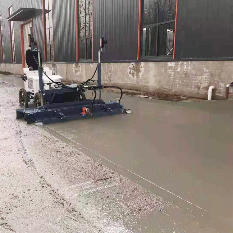
Introduction and working principle of floor concrete laser leveling machine
1. Definition:
1.1 Definition of laser leveling machine: guided by laser, used for leveling and leveling concrete a kind of machine equipment.
1.2 Definition of laser leveling: When large-area concrete floor is being constructed, laser leveling machine is used to vibrate,
level and control the ground elevation of newly poured concrete.
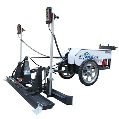
2. Introduction of floor concrete laser leveling machine
The technology principle of the laser leveling machine for floor concrete relies on gasoline generator to generate electricity,
and uses the flat head to drive the laser measurement and control system, computer control system and servo drive system
to complete the leveling work. The whole machine is composed of the fuselage and flat head, and the leveling of concrete
is mainly completed by the flat head part.
3. Preparation
3.1 After the basic level treatment, the laser leveling machine equipment debugging, according
to the original leveling point to a fixed reference level; Lay plastic film, tie steel mesh (according
to the design needs), set the edge die; Set up the laser transmitter, according to the original level
of the floor elevation into the laser leveling machine.
3.2 The concrete shall be transported by commercial concrete and transported to the construction
site by concrete truck.
3.3 Elevation check
Use the hand-held receiver to check the elevation of the floor, introduce the elevation into the laser
leveling machine, adjust the reference point of the leveling machine.
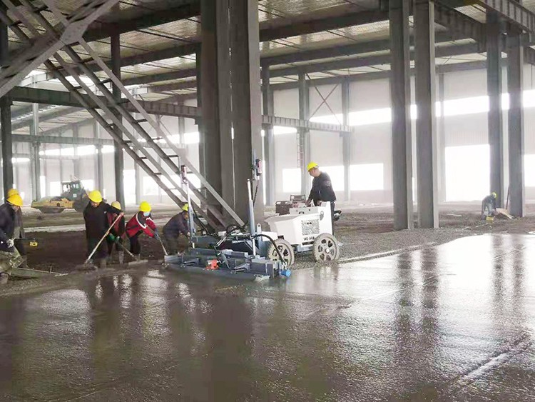
4. Concrete paving
Within the effective construction range of the flat head of the laser leveling machine, the concrete
is first made artificially to the height of 1-2㎝ (the specific height depends on the concrete slump),
and then the vibration, compaction and leveling work is completed by the laser leveling machine
of the floor concrete in one time.
Thanks to All the Friends Who Support and Trust Shandong Vanse Machinery Technology Co., Ltd.
If you want to know more about Shandong Vanse Machinery Technology Co., Ltd. or have any questions, please feel free to contact us:
Our Factory
Shandong Vanse Machinery Technology Co., Ltd.








Share this article

About the Author: Shandong Vanse Machinery Technology Co., Ltd.
Shandong Vanse Machinery Technology Co., Ltd. is a high-tech manufacturer specializing in concrete construction machinery, including laser screeds and related equipment. The company integrates R&D, production, and global sales, with products exported to over 60 countries and widely used in infrastructure projects worldwide.
Previous Post
Next Post
Related Articles
You Might Also Like
How does a concrete laser leveling improve the flatness?
Concrete laser levelings improve flatness by: 1. Utilize laser technology to ensure the flatness and thickness of the concrete surface by precisely controlling the position and height of the laser beam. 2. Automated control technology can realize continuous and automatic leveling operations and improve work efficiency. 3. When performing automatic leveling, there is an accurate reference plane. Generally, when the main focus is to control the height, the tightrope method is suitable; when the main focus is to control the thickness, the floating datum beam method is adopted. Generally, tightrope is used for the bottom layer, and the floating datum beam method is used for the middle layer and surface layer. 4. The leveling machine has a vibration function, which can effectively compact the concrete materials evenly to the required thickness, further improving the flatness. 5. Leveling machines are usually equipped with high-precision sensors and controllers that can monitor and adjust the flatness and height of the concrete surface in real time. Therefore, through the above methods, the concrete laser leveling can effectively improve the flatness of the concrete surface, thereby improving the quality of stinging.Large boom operated laser guided concrete leveling machine
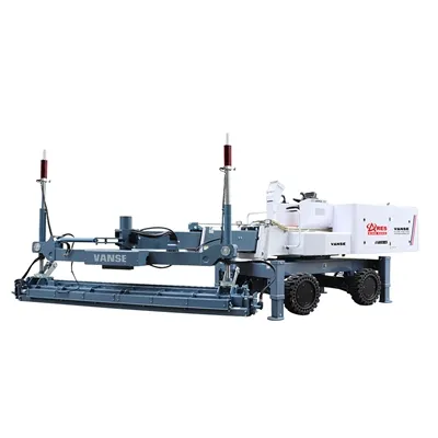
Concrete laser leveling machine is used in large-area floor construction. The ground elevation is easy to control and the ground flatness error is extremely small. Due to the use of laser point-to-point, the entire floor only needs 1-2 reference points for elevation, which can reduce the error caused by multiple reference points. The laser emitter is arranged independently, and the floor elevation is always controlled by the plane formed by the rotating light beam emitted by the laser emitter. As long as the laser emitter is not disturbed, no matter where the Ruifang concrete laser leveling machine goes, it can ensure that the overall elevation of the paved ground is not affected, so that large-area one-time paving can be achieved in floor construction, and the levelness and flatness of the entire floor can be guaranteed. The concrete laser leveling machine uses a laser measurement and control system to control the elevation in real time. There is no need to pull a control line for leveling, and there is no need to support the side template in the middle to control the ground elevation, thereby avoiding the elevation error caused by the vibration of the template (channel steel) during the construction process, and also reducing the elevation error caused by traditional manual block support. Concrete laser leveling machine, used in floor construction, is very easy to achieve one-time overall paving of large-area floor. This paving technology can be divided into blocks as needed, and the whole floor can be completed continuously, making the floor more integrated, which is impossible to achieve with traditional construction technology. When leveling concrete, the concrete laser leveling machine is always in a uniform speed construction state, with a high-frequency vibrator of 4000 times per minute, so that the vibration plate of the leveling head produces uniform high-frequency vibration, making the concrete floor more dense and uniform.Vanse Armor joint
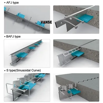
In large-scale concrete floor projects such as industrial plants, logistics and warehousing centers, and large underground garages, joint treatment is the core link that determines the stability and service life of the floor structure. Conventional construction joints, due to their insufficient strength and weak resistance to deformation, are prone to problems such as misalignment, warping, and chipping, which seriously affect the load-bearing performance and functional use of the floor. As a specialized component specifically designed to address such issues, the structural design and application logic of armor joints are of crucial significance for enhancing the quality of floor engineering. Armor joint (also known as armor joint, armored joint, Bama joint, Ba Ma joint, zebra joint) is a composite structural component specially designed for strengthening the joint body of concrete floors. It is usually composed of high-strength metal substrates (such as galvanized steel plates, stainless steel plates, aluminum alloys, etc.), elastic sealing components (EPDM rubber strips, butyl rubber gaskets, etc.) and positioning and fixing systems (shear plates, anchor fasteners, support components). The edge of the seam is a straight metal/composite material cross-section. The upper and lower edges of the seam opening are flush with the ground/wall, without any additional curvature or inclination Angle, and the shape is simple. The edge of the seam is inclined to one side (the slope is usually 3°-5°), or both sides are beveled, forming a groove shape that is "low in the middle and high on both sides". It is advisable to pair it with more metal covers (such as stainless steel and galvanized steel plates). The top adopts an S-shaped curved surface design, formed by stamping steel plates. Combined with the force transmission plate and the telescopic sheath sleeve, it can achieve free expansion and contraction in both longitudinal and transverse directions. Triangular rib design: Triangular reinforcing ribs are welded on the outside of the steel plates of the sub-compartments to enhance the overall rigidity. Thick thrust plate: The thickness of the thrust plate can be selected from 6 to 12mm (material Q355), and it is suitable for heavy-duty areas above 80kN/m². Customized according to the diameter of the column, it is fixed with single-sided support, and the steel plates of the compartments surround the column to form a circular joint. The top edge guard is a flat steel plate, which is cut in the middle along a trapezoidal toothed curve, and the lower part is a punched and bent compartment steel plate and a sawtooth-shaped fixed plate. Cross-shaped, T-shaped, Y-shaped and other combined designs: They are used for the cross-connection of multiple Armor joints. For instance, a cross-shaped node Armor joint can simultaneously connect four straight seams. A stainless steel drainage ditch is integrated at the bottom of the Armor joint, and it is designed in an integrated manner with the steel plate of the compartment. The force transmission plate and the sheath are connected by sliding, allowing the floor to expand and contract freely when the temperature changes. Isolation joint: Also known as "structural separation joint", it is mainly used to achieve physical isolation between the concrete floor and the surrounding building structure. The applicable scenarios are the junctions between the floor and non-floor structures such as walls, reinforced concrete columns, equipment piers and abutments, and embedded part foundations. It separates two structures with different shrinkage coefficients and different load-bearing characteristics through joints, avoiding floor cracking caused by uncoordinated structural deformation. Elastic sealing materials (such as polyurethane sealant) are usually used for filling to ensure the separation effect and water resistance. Cutting joint: Also known as "shrinkage control joint", it is a preset joint body set up to address the problem of irregular cracks that are prone to occur after large-scale concrete pouring. The construction time is after the initial setting of the concrete and before the final setting (usually 24-48 hours after pouring, specifically adjusted according to the strength grade of the concrete). It is cut into shape with a special cutting machine, and the joint depth is usually 1/3 to 1/2 of the floor thickness. The joint spacing is determined according to the strength of the concrete and the ambient temperature (generally 4-6 meters). Its core function is to guide the concrete shrinkage stress to be concentrated and released at the preset joint, avoiding random cracks in the floor. Construction joint/partition joint: A construction joint is a temporary joint set at a preset position due to the excessive area of the floor pouring and the inability to carry out continuous construction at one time, used to divide the pouring sections. The partition joint is a permanent joint body that divides a large area of the floor into fixed-sized partition blocks to control the shrinkage and deformation of the floor in the long term. Essentially, both are "secondary pouring interfaces" of concrete. Such joints, due to the low bonding strength of the concrete joint surface and the uneven distribution of aggregates, have become weak links in the floor structure and are high-risk areas for diseases. Combining the characteristics of concrete structures with the force logic of the floor, the core reasons can be attributed to two points: The construction joint serves as the interface between two concrete pours. Due to the influence of the pouring interval time, the strength development of the concrete poured before and after is not synchronized, and the bonding force at the joint surface is insufficient. When the floor is subjected to vehicle rolling and equipment loads, the blocks on both sides of the joint body are prone to relative displacement, resulting in misalignment (height difference) or warping deformation. After the construction joint is opened, the concrete around the joint is prone to settlement of the internal aggregates under the action of vibration loads (such as vehicle passage and equipment operation), resulting in the separation of mortar and aggregates, and the density and strength of the concrete at the joint decrease. When the load exceeds the load-bearing limit of the joint concrete, edge cracking, corner chipping and other damages are prone to occur, and the damage will gradually expand after it occurs, affecting the structural stability of the entire silo block. Due to the inherent defects of construction joints, in projects with high requirements for the load-bearing capacity and durability of the floor, the use of armored joints has irreplaceable technical value. The metal frame of the armored joint can directly form a rigid connection with the concrete on both sides of the joint body, evenly transmitting the concentrated load at the joint to the surrounding floor, avoiding misalignment and warping caused by concentrated load. Meanwhile, the flexural and compressive properties of the metal substrate can effectively protect the joint concrete and prevent edge chipping caused by aggregate settlement. The elastic sealing components of the armored joint can accommodate the shrinkage deformation of the concrete floor (usually adaptable to ±5mm displacement) and slight settlement of the foundation. This not only prevents the joint from being cracked due to deformation but also ensures sealing performance, preventing oil stains and rainwater from seeping into the foundation. Traditional construction joints need to be repaired on average every 3 to 5 years (such as removing damaged concrete and refitting sealant), and in severe cases, local rework is required. The armored seam, with the anti-corrosion performance of the metal substrate (galvanization, anodizing treatment) and the aging resistance of the sealing components, can have a service life of 15 to 20 years, significantly reducing the frequency and cost of later maintenance. The layout of the armor joints should be determined comprehensively in combination with the floor structure form, load characteristics and usage scenarios. The core should follow the following five technical principles to ensure the effective performance of its functions: Arrange the Armor joints laterally along the load-bearing columns to divide the floor into independent compartments. The size of each compartment must be strictly controlled within 30m×30m. Exceeding this size will cause the shrinkage stress of the concrete to exceed the bearing limit of the armor joint, which is prone to cause cracking in the middle of the silo block. It is strictly prohibited to arrange Armor joints along the direction of directional main channels (such as forklift channels in logistics warehouses and entry and exit lanes in garages) – to prevent vehicle tires from long-term rolling along the seam opening, accelerating the wear of sealing components and deformation of the seam opening. It can be arranged perpendicularly to the direction of the passage to ensure smooth vehicle passage. The length-to-width ratio of floor compartments should be controlled within 1:1.5. If the aspect ratio is too large (such as 1:2 or above), the warehouse blocks are prone to torsional stress due to unidirectional contraction, which may lead to the failure of the Armor joint sealing assembly or the deformation of the metal frame. When armor joints encounter reinforced concrete columns, walls, equipment foundations and other structural bodies, a avoidance distance of 50-100mm should be reserved to prevent the deformation of the structural body and the floor from interfering with each other, which may cause the joint to be squeezed and damaged. Regardless of whether the floor adopts the form of soil foundation bearing or pile foundation bearing, PE sliding film must be laid at the contact surface between the floor and the foundation as well as the contact surface between the floor and the pile cap. PE sliding film can reduce the adhesion between concrete and the base layer, prevent floor cracking caused by foundation settlement, and at the same time provide a stable positioning reference for armor joints, ensuring installation accuracy. In line with the requirements of engineering applications, compared with traditional construction joints and cutting joints, armored joints have the following irreplaceable functional advantages: The metal frame can withstand a uniformly distributed load of 3-5 tons per square meter, making it suitable for high-frequency load scenarios such as heavy-duty forklifts and freight vehicles. The concrete at the joint will not crack due to concentrated loads. It can accommodate ±5mm contraction displacement of concrete floors and ±3mm settlement displacement of the foundation. The elastic sealing components expand and contract synchronously with the deformation, always maintaining the sealed state of the joint. The metal frame forms a "rigid constraint" on the concrete around the joint, preventing aggregate settlement and mortar loss caused by vibration, and fundamentally solving the problems of chipped edges and broken corners. It can be adapted to different types of foundation floors such as soil foundation and pile foundation, and achieve precise fixation in combination with PE sliding film. The installation process is seamlessly connected with the floor pouring procedure, without the need for additional complex processes. The metal substrate undergoes anti-corrosion treatment (galvanizing, anodizing), featuring strong weather resistance and rust resistance. The sealing components are made of anti-aging rubber material, with a service life of over 15 years, significantly reducing the later maintenance cost of the floor. When installing expansion joints, it is essential to meet the requirements of the floor design for levelness and straightness. During the installation process, a level should be used for inspection to ensure that they are precisely vertical in the vertical direction. The force transmission plate should be kept level so that it can slide freely within the plastic sheath when the floor expands and contract freely without generating resistance. In addition, a laser or optical level should also be used for level control and inspection. Step 1 Use nylon thread to position the designed expansion joint. With the assistance of the installation bracket, the straightness and levelness of the Armor joint are adjusted using an optical level until the design value is reached. Step 2 Start installation from the column or wall, and the Armor joint can only be fixed on one side. Use short-threaded steel bars with a diameter of 12 to 14mm to drive into the foundation on one side of the armor joint. Drive two fixed steel bars into each support position, and then weld the armor joint to the fixed steel bars with short steel bars with a diameter of 12mm to 14mm. Step 3 On the first day, pour the unsupported side. The next day, remove the supports and cut off the fixed reinforcing bars above the base layer (to prevent the floor and foundation from being locked and unable to expand or contract freely due to the presence of the fixed reinforcing bars). And pour the concrete on the other side of the armor joint. Step 4 When the curing period of the concrete is over, the edge steel of the armor joint will be gradually and naturally pulled apart. After the contraction stabilizes, remove the garbage in the joint, then fill the elastic adhesive, clean and protect the construction site, and cure for more than 3 days. As a key component for enhancing the quality of concrete floor engineering, the application value of armor joints lies not only in solving the disease problems of traditional joints, but also in improving the long-term stability and load-bearing reliability of the floor structure through standardized structural design and standardized layout principles. For engineering practitioners, it is necessary to strictly follow core principles such as "control of compartment size, reasonable avoidance of passageways, and avoidance of structural structures", and select models in combination with the usage scenarios of the floor and the conditions of the foundation. Only in this way can the technical advantages of the armor joint be fully exerted, and the construction quality and full life cycle value of the floor project be fundamentally improved. Note: The parameters provided in this document are for reference only and are not mandatory. Due to differences in technical characteristics between different brands and models of laser levelers, please consult the manufacturer for a suitable solution before actual operation. This reference document assumes no responsibility for any issues arising from failure to follow the manufacturer's instructions.