Technical Knowledge
What are the common mistakes in concrete laser leveling operations, and how can faults be quickly resolved?
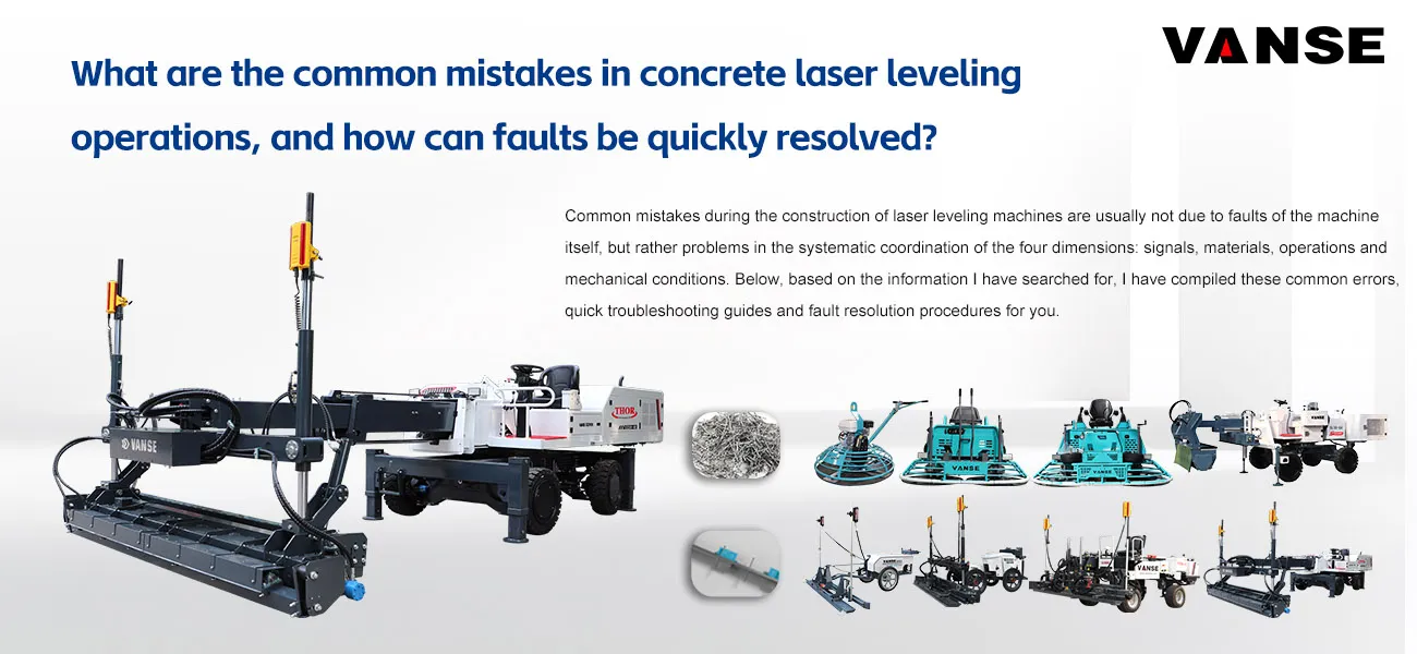
Common mistakes during the construction of laser leveling machines are usually not due to faults of the machine itself, but rather problems in the systematic coordination of the four dimensions: signals, materials, operations and mechanical conditions. Below, based on the information I have searched for, I have compiled these common errors, quick troubleshooting guides and fault resolution procedures for you.
🚧 Four Common Mistakes in Laser Alignment Construction and Their Solutions
| Error Categories | Typical phenomenon | The root cause | Quick solution |
| 1. Signal and System Error | The overall ground elevation has shifted, wave-like patterns have appeared, or the machine operation has been irregular. | The laser transmitter is installed on unstable foundations (such as soft soil, vibrating floor slabs); the signal is blocked or interfered with by strong light or reflective objects (glass, stainless steel); strong winds cause the transmitter to shake. | Check immediately: Ensure that the tripod of the transmitter is firmly fixed on a solid base. |
| Physical isolation: Remove any obstacles between the receiver and the transmitter, and install a windproof cover or counterweight on the transmitter. | |||
| Avoid interference: Keep the cable of the concrete pump truck away from the transmitter support. | |||
| 2. Concrete material error | The slump variation is significant, resulting in some areas of the ground being too high (too dry) or too low (too soft); "cold joints" or inconsistent hardness occur at the seams. | The slump of the concrete does not match the laser leveling machine. The optimal range is usually 140mm ± 20mm. If it is too dry (< 100mm), the machine cannot move; if it is too thin (> 200mm), it is prone to segregation. | Source control: At the mixing station, the mix ratio is strictly controlled. The slump of each truckload of concrete upon arrival is measured, and if it fails to meet the standards, it will be rejected or the mix will be adjusted. |
| The supply of concrete was discontinuous, and there was a significant difference in the performance of the concrete between the front and rear vehicles. | Ensure continuous pouring: The feeding rhythm is reasonably arranged to avoid long intervals. | ||
| 3. Operator's mistake | After leveling, the ground has knife marks, waves, or edges that have collapsed. | Improper control of the working head: If too much material is piled up before leveling the head (exceeding half the height of the spiral working head), it causes excessive resistance and the machine body lifts up; if there is too little material, it cannot level the low areas. |
Control the uniform speed and material quantity: The operator and the discharging workers closely cooperate, maintaining an excess of approximately 2-3 centimeters of material before reaching the leveling head.
Using marking lines for assistance: Draw lines on the ground and ensure that the overlap width is consistent each time. |
| Excessive speed: The hydraulic system cannot respond in time. Generally, it is recommended to maintain a speed of 3-5 meters per minute. | |||
| Incorrect overlap width: If the overlap between adjacent processes is too wide or too narrow, the standard overlap width is usually 15-30 centimeters. | |||
| 4. Mechanical state error | Regular stripes appear on the ground, or the machine operates with sluggishness and tremors. | Inconsistent tire pressure: A large pressure difference between the left and right wheels causes the leveling head to sway left and right, resulting in wave patterns. | Daily start-up inspection: Measure and standardize the tire pressure of all four wheels. |
| Wear of vulnerable parts: Uneven wear of the scraper plate and base plate will cause "grooves" to appear, and wear of the spiral feeder affects the uniformity of the material distribution. | Daily maintenance: Clean thoroughly after each use, especially paying attention to the concrete on the screws and scrapers to prevent damage to the components after hardening. Check all bolts and tighten them. | ||
| Hydraulic system response lag: High hydraulic oil temperature or blocked valve groups cause delayed execution of instructions. | Critical gap inspection: Ensure that the installation gaps of components such as scrapers and augers meet the standards (for example, the scraper is 1/4 inch higher than the auger). |
⚙️ Quick Fault Diagnosis and Troubleshooting Guide
When problems occur during construction, follow the principle of "from outside to inside, from simple to complex" to conduct a rapid diagnosis.
Step 1: Safety inspection and preliminary investigation (the root cause of most problems)
Immediately stop the machine, turn off the laser transmitter, and ensure safety.
Check if the "eyes" are clean: Clean the sensing panel of the laser receiver and the window of the laser transmitter to ensure there is no cement slurry or dust covering.
Check if the "energy" is sufficient: Confirm that the laser transmitter, receiver, and remote control batteries are fully charged, and all cable plugs are securely connected.
Step 2: Step-by-step investigation based on the fault phenomenon
Situation A: No signal or weak signal from the receiver
Confirm the transmitter status: Is it turned on and in rotation mode? Is the horizontal bubble centered?
Check height and position: Is the receiver within the effective working height range of the laser transmitter? Move the movable receiver closer to the transmitter for testing.
Exclude interference: Is there strong sunlight direct exposure? Try installing a shading cover.
Situation B: Unstable signal, machine shakes up and down
Check the foundation: Is the tripod of the transmitter stable? Is the ground vibrating?
Check mechanical connections: Are the connections between the receiver and the mast, and the mast and the vehicle body firm? Is the gap at the leveling head too large?
Check electromagnetic interference: Are the laser system cables bundled with power lines and hydraulic pipes? They should be arranged separately.
Situation C: Continuous deviation in leveling accuracy (inaccurate elevation)
Calibrate the laser transmitter: This is the most critical step! Use the random accompanying calibration tools to check and calibrate the horizontal accuracy of the transmitter.
Check reference points: Reconfirm the absolute elevation of the construction benchmark points (marks) to see if it is correct.
Check mechanical linkage: Manually operate the hydraulic lifting, check if the cylinder movements are smooth and powerful, and if there is any jamming or internal leakage.
Situation D: Abnormal walking system (unable to walk, one side weak, walking deviates)
Check emergency stop and mode: Has the emergency stop button been pressed? Is the working mode correct?
Check mechanical jamming: Are the walking wheels or tracks stuck by concrete blocks?
Check hydraulic system: Is the hydraulic oil level normal? For single-sided faults, try swapping the hydraulic pipes on both sides. If the fault phenomenon shifts, it can be determined to be a problem with the motor or valve group.
🚑 Standardized Fault Resolution Procedure
Establish a standard procedure to minimize the impact of faults on construction:
Fault reporting: The operator discovers a fault and immediately reports it, describing the phenomenon and the time.
Quick analysis: The maintenance team quickly locates the cause based on the phenomenon and the above troubleshooting steps, and formulates a plan.
Supplies and tools: On-site should always have spare parts (such as sensors, sealing rings, filter elements, etc.) and specialized tools readily available.
Fault repair: Carry out the repair according to the plan.
Record and analysis: Record the type of fault, the cause, and the solution method. Regularly analyze to avoid recurrence.
💡 Expert advice: How to fundamentally avoid problems?
Three checks every day: Before starting work, check the installation point of the laser transmitter, tire pressure, and the slump of the first batch of concrete.
Dual insurance: 2 meters behind the leveling machine, arrange workers to use a 3-meter scraper for fine adjustment to eliminate small defects at the machine's turning or joint.
Technical upgrade: Consider introducing equipment with remote monitoring and fault diagnosis systems. Such systems can monitor key parameters in real time, achieve preventive maintenance, and issue warnings before faults occur, turning "unexpected shutdowns" into "planned maintenance", greatly ensuring the construction schedule.
If you encounter specific abnormal phenomena during the construction (such as specific patterns of ripples on the ground, or a complete failure of a certain action), please tell me more detailed information, and I can help you conduct more targeted analysis. Contact us NOW
Note: The parameters provided in this document are for reference only and are not mandatory. Due to differences in technical characteristics between different brands and models of laser levelers, please consult the manufacturer for a suitable solution before actual operation. This reference document assumes no responsibility for any issues arising from failure to follow the manufacturer's instructions.
Thanks to All the Friends Who Support and Trust Shandong Vanse Machinery Technology Co., Ltd.
If you want to know more about Shandong Vanse Machinery Technology Co., Ltd. or have any questions, please feel free to contact us:
Our Factory
Shandong Vanse Machinery Technology Co., Ltd.








Share this article

About the Author: Shandong Vanse Machinery Technology Co., Ltd.
Shandong Vanse Machinery Technology Co., Ltd. is a high-tech manufacturer specializing in concrete construction machinery, including laser screeds and related equipment. The company integrates R&D, production, and global sales, with products exported to over 60 countries and widely used in infrastructure projects worldwide.
Previous Post
Next Post
Related Articles
You Might Also Like
Can concrete topping spreaders handle different types of additives (e.g., color pigments, anti-slip agents) for floor projects
Yes, they absolutely can, but with a few technical "fine print" warnings. While these machines are designed for dry-shake hardeners (which are essentially a pre-mixed blend of cement, sand, and additives), you can certainly use them to distribute specific components like pigments or anti-slip agents-provided you respect the machine's mechanical limits. Here is how concrete topping spreaders handle various additives and the adjustments you need to make. Most "color" in industrial floors isn't pure pigment; it's a Color Hardener (pigment + cement + fine aggregate). The Spreader's Role: It is the only way to get a perfectly uniform color. Hand-tossing color usually results in "leopard spots." The Risk: Pure, raw pigment is often too fine (like flour). If you put pure pigment in a spreader, it may "bridge" (clump together) in the hopper and refuse to fall through the rotor. The Fix: Ensure the pigment is part of a engineered dry-shake mix. If you must use pure pigment, it should be blended with a carrier (like fine sand) to give it enough "weight" to flow through the machine. For loading docks or wet processing areas, you might spread Silicon Carbide or Aluminum Oxide. Handling: These materials are much denser and "grittier" than standard hardeners. Machine Wear: These are essentially sandpaper for your equipment. If you are running high volumes of anti-slip agents, you will notice accelerated wear on the rubber seals and the discharge rotor. Distribution: Because these grains are heavy, they drop very fast. You usually need to tighten the discharge gap on the spreader to prevent "dumping" too much material in one spot. Additive Type Material Examples Spreader Compatibility Key Challenge Metallic Aggregates Iron filings, steel grit Excellent High weight; requires heavy-duty motors. Anti-Slip Silicon Carbide, Quartz Good Highly abrasive; wears down internal parts. Reflective Glass beads, "Sparkle" grain Moderate Very fragile; can "crush" in the rotor. Pure Pigment Iron oxide powders Difficult Clumping and "dusting" (blown away by wind). If you are switching from a high-visibility color (like "Safety Red") to a standard grey hardener, a simple shake-out isn't enough. The Danger: Residual pigment trapped in the rotor corners will "bleed" into the next project for the first 100 feet. The Fix: Use a shop-vac and a stiff brush to clean the internal discharge vanes. Some operators run a "sacrificial" 25 kg bag of plain sand through the machine to scrub the pigment out before starting the next color. Additives like pure pigments are extremely hygroscopic (they suck moisture out of the air). If you leave specialized additives in the hopper during a lunch break or a rain delay, they can "cake" onto the rotor. The Rule: Only load what you are about to spread immediately. Not all additives weigh the same. 1 Liter of Steel Aggregate weighs much more than 1 Liter of Glass Beads. The Test: Before starting the actual floor, run a "10-foot test" on a piece of plastic or a dry section of the slab. Weigh the material dropped to ensure your kg/㎡ (or lb/ft^2) matches the project spec. Integrated Blends: Yes, flawlessly. This is what they are built for. Raw Abrasives: Yes, but expect higher maintenance on the machine. Fine Powders: No, unless blended with a carrier to improve flow. Pro Tip: When spreading reflective beads or very fine anti-slip grains, lower the discharge height of the spreader head as much as possible. Even a light breeze in a warehouse can blow 20% of your expensive additives away before they even hit the wet concrete. Would you like me to find the recommended "Drop Rates" (kg/㎡) for standard VS heavy-duty industrial wear layers? Contact us NOW Note: The parameters provided in this document are for reference only and are not mandatory. Due to differences in technical characteristics between different brands and models of laser levelers, please consult the manufacturer for a suitable solution before actual operation. This reference document assumes no responsibility for any issues arising from failure to follow the manufacturer's instructions.What is the proper maintenance schedule for the boom sections of the concrete laser leveling machine?
The boom (also known as the telescopic boom or large boom) of the concrete laser leveling is its core structure and power transmission component, bearing the vibrating rammer and scraper. The reliability of its maintenance is directly related to the accuracy, service life and construction safety of the equipment. The following is a systematic and comprehensive correct maintenance plan for the boom section, covering daily, regular and professional-level maintenance. This is the most fundamental and crucial step in preventing malfunctions. Structural visual inspection: Carefully inspect the main body of the boom, the connection points of each section, and the hinge seats connected to the main unit for any visible cracks, open welds, severe deformations or corrosion. Focus on inspecting areas with stress concentration. Fastener inspection: Use manual tools to check whether all key bolts (especially hinge pin shaft bolts, boom extension and retraction fixing bolts, and cylinder connection pin bolts) are loose. Tighten regularly according to the torque specified by the manufacturer. Grease lubrication: Apply grease to all lubrication points (grease nipples) until all the old grease is completely squeezed out. Including: All articulated pin shafts Boom telescopic slide/slider (if any) The connection support between the vibrator and the boom Preliminary inspection of the hydraulic system: Check whether there are scratches, dents or leaks on the surface of the piston rods of the boom lifting and telescopic cylinders. Check whether there is any oil leakage at the hydraulic pipeline joints. Thorough cleaning: Use a high-pressure water gun (with moderate pressure, avoid direct impact on bearing seals and electrical components) to remove all solidified concrete slurry and debris from the boom, scraper, and tamper plate. Residual concrete will increase the load, disrupt the dynamic balance and cause corrosion. Inspect the slider/slide: After cleaning, check the wear condition of the slider of the boom extension mechanism (usually made of wear-resistant polymer materials), and remove the sand particles in the slide. Proper storage: Retract and lower the boom, place it on a stable support, and release the stress. Avoid storing for a long time in a fully extended or suspended state. Replenish the daily lubrication points and ensure the use of the correct type of grease specified in the equipment manual. For sliding contact surfaces without grease nipples, a thin layer of grease can be applied to prevent rust. Use a torque wrench to systematically retighten all key bolts of the boom structure strictly in accordance with the torque values provided by the manufacturer. Vibration is the primary cause of bolt loosening. Cylinder: Check the sealing condition of the cylinder more carefully and inspect whether the piston rod is bent. Pipes and joints: Inspect all hydraulic hoses for signs of wear, bulging, cracking or friction with structural components. Fix it in time with a rubber hose protective sleeve or re-bind it. Hydraulic oil status: Check the oil level and quality (color, odor, and presence of foam) of the entire machine's hydraulic oil. Contaminated or deteriorated hydraulic oil can damage the valve groups that control the movement of the boom. For equipment used at high intensity, it is recommended to use professional methods such as magnetic particle testing or ultrasonic testing to inspect key welding areas and stress zones, in order to detect micro-cracks that are invisible to the naked eye. Disassemble and inspect key pin shafts and bushings: Disassemble the main hinged pin shafts, check their wear and scratches, and measure the diameter. Check the wear clearance of the bushing/bearing. If it exceeds the wear limit, it must be replaced. Check the deformation of the boom: Use professional instruments or the wire pulling method to check whether the straightness and parallelism of the boom are within the allowable range. Replace worn parts: Replace worn telescopic sliders, scraper cutting edges, ramming plate bottom plates and other vulnerable parts. Hydraulic system maintenance: Replace hydraulic oil and filter elements, and clean the hydraulic oil tank. Check and adjust the working pressure and synchronization of the boom control valve group. Thoroughly remove the rust from the areas where the paint layer has peeled off and rusted, and reapply the same grade of anti-rust primer and topcoat as the original factory. High-intensity continuous operation: Shorten the interval between lubrication and inspection (such as adding one intermediate inspection per shift). Corrosive environments (coastal areas, near chemical plants) : Enhance cleaning and carry out anti-corrosion treatment more frequently. Extreme temperature difference environment: Pay attention that the type of hydraulic oil and grease must meet the temperature requirements. After cold start, low-speed preheating operation is required. Establish a maintenance log: record in detail the date of each maintenance, the project, the replaced components, the problems found and the handling measures. This is helpful for tracking the status of devices and predicting their lifespan. Standardized operation: The maintenance plan must be combined with standardized operation. Operators should avoid: Use the boom to forcefully push materials or collide. Driving at high speed or turning when the boom is not lifted. Allow the equipment to extend, retract or lift before it has completely stopped. Overloading or operating beyond the designed slope. Cleanliness is the foundation: preventing concrete consolidation and corrosion. Lubrication is key: reducing wear, preventing abnormal noise and jamming. Fastening is a guarantee: preventing structural loosening and accidents. Inspection is prevention: Through daily visual inspection and regular professional checks, potential hazards can be eliminated in their infancy. The records are based on: achieving traceable and scientific preventive maintenance. Strictly adhering to the specific regulations and suggestions in the "Operation and Maintenance Manual" provided by the equipment manufacturer is the fundamental basis for formulating and implementing any maintenance plan. When any undetermined abnormalities (such as abnormal noise, slow movement, or unexplained deviations) are detected, the machine should be stopped immediately and professional technicians should be contacted for diagnosis. Note: The parameters provided in this document are for reference only and are not mandatory. Due to differences in technical characteristics between different brands and models of laser levelers, please consult the manufacturer for a suitable solution before actual operation. This reference document assumes no responsibility for any issues arising from failure to follow the manufacturer's instructions.How to maintain a large pavement concrete trowel?
Ride-on trowels have now basically become the main equipment for pavement polishing. They are loved by everyone because of their simple and convenient operation and fast operation speed. Ride-on trowels with such good operating results also need to be well maintained on a daily basis. To work, it is correct and effective to start from these aspects. 1. Clean the fuselage regularly, and clean the sticky concrete on the fuselage and the trowel grinding disc promptly after the construction is completed to avoid damage to the inside of the machine; 2. The trowelling machine constantly vibrates and changes speed when working. Some bolts may become loose. The tightness should be checked frequently and adjusted in time; 3. During use, lubrication and maintenance of all parts of the machine must be done frequently to avoid wear and tear of the machine parts; 4. When the trowel is not in use, it should be placed on a flat ground to prevent the trowel disc from deforming and affecting its next use; 5. Check the oil levels of various oils frequently and add them in time when insufficient. Taking good maintenance measures for your trowel machine will not only maintain the working efficiency of the machine, but also effectively extend the life of the machine and allow your project to be completed ahead of schedule. Therefore, all aspects of maintenance cannot be ignored.