Technical Knowledge
Diagnosis and Solution of Abnormal Walking System of Concrete Laser Leveling Machine
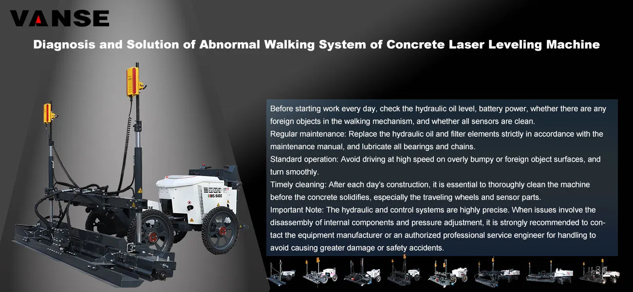
The walking system of the Concrete Laser Leveling is one of its core functions. Once it malfunctions, it will directly affect the construction efficiency and the flatness of the floor. The following is a systematic review of the diagnostic steps and solutions for abnormal walking systems for you.
Ⅰ. Classification of Fault Phenomena
First, make a preliminary classification based on different fault phenomena:
Completely unable to walk: The leveling machine is completely stationary.
Weak walking/Slow speed: Can walk, but lacks power and cannot reach the set speed.
Unstable walking/shaking: Stammering during walking or severe shaking of the body.
Abnormal walking on one side: One side is normal, while the other side is motionless, weak or in the wrong direction.
Walking deviation: Unable to walk in a straight line, automatically veers to one side.
Ⅱ. Systematic Diagnostic Process and Solutions
Follow the principle of conducting the investigation from simple to complex and from the outside to the inside.
Step 1: Preliminary appearance and basic inspection
Emergency stop switch and mode selection
Diagnosis: Check whether the emergency stop switch on the operation console or remote control has been pressed and whether the working mode (such as manual/automatic) has been selected correctly.
Solution: Release the emergency stop switch and select the correct working mode.
Power supply and line connection:
Diagnosis: Check whether the main power switch and battery terminals are loose, corroded or have insufficient power (for battery-powered models). Check whether the plugs at the main control cabinet and the walking motor are loose.
Solution: Tighten all terminal blocks, clean the battery terminals, charge the battery or replace it. Make sure all the plugs are securely connected.
Jamming of mechanical transmission components
Diagnosis: Check whether the walking wheels (tracks), drive shafts, chains or gears are jammed by solidified cement, crushed stones or other foreign objects.
** Solution ** : Immediately stop the machine and thoroughly clear all obstructions. Check the lubrication condition of the chain or gearbox and add or replace the specified grease if necessary.
Step 2: Hydraulic System Diagnosis (Common Fault Points)
If there are no issues found during the initial inspection, focus on checking the hydraulic system.
Hydraulic oil level and oil quality
Diagnosis: Insufficient hydraulic oil can cause the pump to run dry, resulting in weak or no movement during movement. Deteriorated oil (turning black, foaming, or having metal shavings) can damage hydraulic components.
Solution: Check the oil level while the machine is shut down and replenish it to the specified mark. If the oil quality is substandard, the hydraulic oil and filter element of the original factory-specified model must be completely replaced.
Walking motor and drive pump
Diagnosis (Unilateral abnormality) : If only one side of the walking is abnormal, you can try to swap the hydraulic pipelines of the walking motors on both sides. If the fault phenomenon then shifts to the other side, it indicates that the walking motor or pump on the original side is faulty.
Solution: Please contact professional maintenance personnel. It may be necessary to inspect or replace the walking motor, variable pump or related control valves. This job requires professional knowledge and tools. Do not disassemble it by yourself.
Hydraulic system pressure
Diagnosis: Use a hydraulic pressure gauge to check whether the overflow pressure of the main safety valve and the walking circuit of the system has reached the specified value. Low pressure can lead to weakness when walking.
Solution: Have a professional technician adjust the corresponding relief valve to the standard pressure. Do not adjust it at will, otherwise the hydraulic system may be damaged.
Step 3: Control system and sensor diagnosis
For laser leveling machines that adopt advanced control systems.
Laser control system
Diagnosis: Check whether the laser transmitter is working properly and whether the signal is stable. Check whether the laser receiver on the leveler is clean and firmly installed. Signal loss or instability can cause the machine to move in confusion or stop.
Solution: Ensure that the laser transmitter is stably set up and the signal covers the entire construction area. Clean the laser receiver rod and sensor head. Recalibrate the system.
Control module and sensor
Diagnosis: Observe whether there are any fault code alarms on the control panel. Check whether the walking speed sensor, Angle sensor, etc. are damaged or the circuit is disconnected.
Solution: Check the cause according to the fault code manual. Check and plug in the sensor wiring tightly. Replace it if any damage is found.
Remote control/line controller
Diagnosis: Weak signal, insufficient battery power or internal faults of the remote control can cause instructions to fail to be sent correctly, resulting in abnormal walking.
Solution: Check the battery level of the remote control and try frequency matching or restarting. If possible, switch to the line control mode for comparative testing to determine whether the problem lies with the machine or the remote control.
Ⅲ. Quick Reference Table of Common Fault Phenomena and Targeted Solutions
| Fault phenomenon | Possible reasons | Solution |
| Completely unable to walk | 1. The emergency stop switch is activated | 1. Release the emergency stop switch |
| 2. Main power supply disconnected/Battery discharged | 2. Check and connect the power supply/charge | |
| 3. Failure of the main hydraulic pump | 3. Overhaul the main pump | |
| 4. Control signal interruption | 4. Check the remote control, receiver and wiring | |
| Weakness in walking | The hydraulic oil level is too low or the oil quality is poor | 1. Add or change the oil |
| 2. The hydraulic filter element is clogged | 2. Replace the hydraulic filter element | |
| 3. System pressure is too low | 3. Adjust the pressure by professionals | |
| 4. Leakage inside the walking motor or pump | 4. Inspect or replace hydraulic components | |
| One side not moving/weak | The track/wheel on this side is mechanically jammed | 1. Remove foreign objects |
| 2. The walking motor on this side is faulty | 2. Swap the hydraulic pipelines for testing and then carry out the repair after confirmation | |
| 3. The valve core of the control valve on this side is stuck or damaged | 3. Clean or replace the valve assembly | |
| 4. The speed sensor on this side is faulty | 4. Check or replace the sensor | |
| Shaking/Unstable walking | There is air in the hydraulic system | 1. Perform the exhaust operation |
| 2. The signal of the flow/speed sensor is unstable | 2. Check the sensors and circuits | |
| 3. Hydraulic oil contamination leads to discontinuous valve core operation | 3. Replace the hydraulic oil and filter element | |
| Walking off course | 1. The laser signal is inaccurate | Recalibrate the laser system |
| 2. The tension of the tracks on both sides is inconsistent | 2. Adjust the tracks to the same tension | |
| 3. The bearing of one of the walking wheels is damaged | 3. Replace the damaged bearing | |
| 4. Calibration error of the control system | 4. Re-perform the walking calibration |
Ⅳ. Safety Precautions and Daily Maintenance
Before starting work every day, check the hydraulic oil level, battery power, whether there are any foreign objects in the walking mechanism, and whether all sensors are clean.
Regular maintenance: Replace the hydraulic oil and filter elements strictly in accordance with the maintenance manual, and lubricate all bearings and chains.
Standard operation: Avoid driving at high speed on overly bumpy or foreign object surfaces, and turn smoothly.
Timely cleaning: After each day's construction, it is essential to thoroughly clean the machine before the concrete solidifies, especially the traveling wheels and sensor parts.
Important Note: The hydraulic and control systems are highly precise. When issues involve the disassembly of internal components and pressure adjustment, it is strongly recommended to contact the equipment manufacturer or an authorized professional service engineer for handling to avoid causing greater damage or safety accidents.
Note: The parameters provided in this document are for reference only and are not mandatory. Due to differences in technical characteristics between different brands and models of laser levelers, please consult the manufacturer for a suitable solution before actual operation. This reference document assumes no responsibility for any issues arising from failure to follow the manufacturer's instructions.
Thanks to All the Friends Who Support and Trust Shandong Vanse Machinery Technology Co., Ltd.
If you want to know more about Shandong Vanse Machinery Technology Co., Ltd. or have any questions, please feel free to contact us:
Our Factory
Shandong Vanse Machinery Technology Co., Ltd.








Share this article

About the Author: Shandong Vanse Machinery Technology Co., Ltd.
Shandong Vanse Machinery Technology Co., Ltd. is a high-tech manufacturer specializing in concrete construction machinery, including laser screeds and related equipment. The company integrates R&D, production, and global sales, with products exported to over 60 countries and widely used in infrastructure projects worldwide.
Previous Post
Next Post
Related Articles
You Might Also Like
Quality Control Requirements for Ultra-Large Laser-Leveled Wear-Resistant Concrete Floors
Ultra-large laser-leveled, wear-resistant concrete floors combine precise laser leveling technology with the enhanced properties of wear-resistant materials. They are widely used in industrial plants, logistics warehouses, large commercial spaces, and other applications. Quality control must be implemented throughout the entire process: design, materials, construction, maintenance, and acceptance. The core goal is to achieve high flatness, high wear resistance, low cracking, and strong durability. The following details the quality control requirements from seven key perspectives: Ultra-large flooring (typically >1000 m2) is prone to cracking due to concrete shrinkage. Therefore, the initial design plan must focus on deformation control and construction feasibility. Specific requirements are as follows: Compartment Area: The size of a single compartment should be considered based on concrete shrinkage characteristics, typically ranging from 6m x 6m to 12m x 12m (aspect ratio ≤ 1.5) to avoid thermal stress cracking caused by excessive area. Joint Type Requirements: Expansion joints should be 8-12mm wide and ≥ 1/3 the floor thickness (or continuous). Use foam strips and sealant to prevent debris from entering and mitigate deformation. False Joint Installation: For long floors (e.g., >30m in length), false joints (cut depth 5-8mm) with intervals of ≤ 6m between compartment joints should be added to guide shrinkage cracks along the false joints. Clearly define the floor design elevation (±0.000 relative to the reference point). The laser leveling's reference line must be calibrated with a high-precision level (±1mm accuracy) to avoid cumulative errors. Flatness requirements: According to the "Code for Design of Building Floors" GB 50037, the allowable flatness deviation for industrial floors is ≤3mm/2m (laser detection), and for commercial floors, ≤2mm/2m. Strength Grade: Determined based on the application scenario. Industrial plants (load-bearing capacity 5-10t): ≥C30; logistics warehouses (load-bearing capacity >10t): ≥C35. Slump: Laser leveling requires low-slump concrete, controlled within 120±20mm (on-site measurement) to avoid delamination and sanding caused by excessive slump. Crack Resistance: Add polypropylene fiber (0.9-1.2kg/m³) or steel fiber (20-30kg/m³) to reduce plastic shrinkage cracking. Use a slow-setting water-reducing admixture to extend the initial setting time (≥6h) to ensure continuous construction over large areas. Material Type Core Control Indicators Inspection Requirements Commodity Concrete 1. Strength Grade (C30/C35); 2. Slump (120 ± 20 mm); 3. Initial Setting Time (≥ 6 hours); 4. Air Content (≤ 3%) One set of compression test blocks must be collected for every 500m³ of material. Slump must be measured on each truck upon arrival; any exceeding the standard must be immediately returned. Metal Wear-Resistant Materials 1. Metal Aggregate Content (≥ 60%, e.g., corundum, chromite sand); 2. Mohs Hardness (≥ 6); 3. Compressive Strength (≥ 80 MPa) Three sets of samples must be collected from each batch to test for hardness and strength. The appearance must be free of lumps and impurities. Non-Metal Wear-Resistant Materials 1. Quartz Sand Particle Size (0.3-1.2 mm, Continuous Grading); 2. Abrasion Resistance (Abrasion Loss ≤ 0.3 g/cm²); 3. Color Consistency Material within the same batch must exhibit no color variation. Abrasion resistance must be tested in accordance with GB/T 12988, "Test Method for Abrasion Resistance of Building Floor Materials." Auxiliary Materials 1. Polypropylene Fiber (Length 6-12 mm, Tensile Strength ≥ 300 MPa); 2. Sealant (Elastic Modulus ≥ 0.8 MPa) Fibers must be evenly dispersed and free of agglomerates. Sealant must comply with GB/T 14683, "Building Sealing Materials." Laser leveling is key to ensuring floor flatness. The entire "concrete paving – laser leveling – vibration – slurry preparation" process requires strict control. Specific requirements include: Construction Preparation and Equipment Calibration The concern laser leveling machine must be preheated one hour in advance. Use two independent reference points to calibrate the laser transmitter (with an error of ≤0.5mm) to avoid deviation from a single reference point. Base Preparation: The base layer (such as lime soil or gravel cushion) must be compacted (compaction degree ≥95%), with a surface flatness of ≤5mm/2m and no water accumulation or loose debris. Apply plastic sheeting (thickness ≥0.12mm) to prevent water absorption from the base layer, which could lead to rapid dehydration of the concrete. Paving Order: Divide the area by the gaps between the paving bays, and proceed from far to near, high to low, to avoid trampling on the already paved concrete. Thickness Control: Pave according to the designed thickness (usually 100-150mm) + 5% of the void thickness. Control the laser leveling speed between 0.8-1.2m/min, ensuring sufficient vibration with the vibrator (vibration frequency ≥ 50Hz) to remove air bubbles. Smoothness Monitoring: After every 50㎡ of paving, check the smoothness with a 2m straightedge and a feeler gauge. If the deviation exceeds 3mm, immediately use the laser leveling to level the surface. Manual repairs are strictly prohibited. Spreading and finishing of wear-resistant materials Spreading Timing: Before the concrete begins to set (press the concrete surface with your finger, leaving a 3-5mm indentation). Spread the concrete in two passes (60% for the first pass and 40% for the second pass) to avoid sinking if spread too early or preventing the concrete from bonding if spread too late. Spreading Uniformity: Use a "plum blossom dot" method with manual leveling to ensure the material dosage per square meter meets the design (usually 5-8kg/square meter for wear-resistant metals and 3-5kg/square meter for non-metals). Mechanical Finishing: After the first pass, smooth the surface with a disc trowel (150-200 rpm). After the second pass, finish the surface with a blade trowel (250-300 rpm). The surface should be free of smear marks, exposed areas, and have a uniform gloss. Large-scale floors are most susceptible to "plastic shrinkage cracks" (during construction) and "thermal shrinkage cracks" (during curing). These cracks must be controlled from three perspectives: Controlling Plastic Cracks During Construction Environmental Control: In high temperatures (>30°C) or strong winds (>5m/s), erect a sunshade and apply moisturizing spray (the temperature difference between the water and concrete should be ≤10°C) to prevent rapid surface water loss. Pre-setting Treatment: Within 30 minutes after paving, vibrate the concrete a second time using a vibrating beam to eliminate surface bubbles. If fine cracks are found, immediately re-press and close them with a trowel. Curing Time: 1-2 hours after finishing (initial setting of the surface), immediately cover with a moisture-retaining film and geotextile (or flame-retardant straw mat). Avoid direct sunlight exposure. Curning Time: ≥7 days for ordinary concrete, ≥14 days for concrete with admixtures or waterproofing. Water 3-4 times daily (keep the geotextile moist), and avoid sudden temperature drops. (If the temperature difference between day and night exceeds 15°C, cover with an insulation layer.) Post-Crack Treatment Fine cracks (width < 0.3mm): Seal with epoxy putty. Wide cracks (width ≥ 0.3mm): Cut a V-shaped groove (depth ≥ 10mm, width ≥ 8mm) along the crack, clean it, fill it with elastic sealant, and smooth the surface with wear-resistant material. After construction (during the curing period), the floor is susceptible to external damage and requires strict protective measures: Premature loading is prohibited: No personnel (except maintenance personnel) are allowed to move about within 7 days of curing, and no vehicles (including carts) are allowed to pass through within 14 days. Loading can only be carried after the floor has fully reached its design strength (28 days). Machinery protection: Machinery that requires operation on the floor (such as forklifts) must have rubber mats on their tires. Sharp turns and sudden braking are strictly prohibited to avoid scratching the surface. Pollution protection: Paint, engine oil, and other chemicals must not be piled on the floor. If spilled, rinse immediately with clean water (use a dedicated degreaser to remove oil stains) to prevent penetration and corrosion. Acceptance must be conducted in accordance with the "Concrete Structure Construction Quality Acceptance Code" (GB 50204) and the "Building Floor Construction Quality Acceptance Code" (GB 50209). Core testing items are as follows: Acceptance Items Quality Requirements Testing Methods: Smoothness Tolerance: ≤3mm/2m (industrial flooring), ≤2mm/2m (commercial flooring) Laser flatness tester (measure one point per 100 m2) or 2m straightedge + feeler gauge (measure three points per 50 m2). Abrasion Resistance Abrasion loss: ≤0.15g/cm² for metal wear-resistant flooring, ≤0.3g/cm² for non-metallic flooring Testing with an abrasion resistance testing machine in accordance with GB/T 12988 (measure one point per 1000 m2). Strength Concrete compressive strength: ≥ design value (C30/C35), surface hardness (rebound value): ≥35MPa (metal wear-resistant flooring) 28-day compression test of concrete specimens; surface hardness test with a rebound hammer (measure 10 points per 500 m2). Appearance Quality 1. No exposed surfaces, sanding, or hollows; 2. Uniform color variation (no significant differences within the same batch); 3. Crack width: <0.3mm Visual inspection (full inspection); tapping with a small hammer to detect hollows (measure 10 points per 100 m2, hollow rate ≤ 2%). Partition Joints/Expansion Joints Joint width and depth must meet design requirements, sealant must be fully applied without flaking, and no foreign matter must be present. Measurement with a tape measure (measure one point every 10 m); visual inspection of the sealant appearance. Common Problems Causes: Preventative Measures Surface Sanding 1. Excessive concrete slump; 2. Premature application of wear-resistant material; 3. Inadequate curing; Control slump at 120 ± 20 mm; apply wear-resistant material at the time of initial setting; apply moisturizing coating within 1 hour of finishing. Excessive Flatness 1. Uncalibrated laser leveling; 2. Uneven base layer; 3. Uneven paving thickness; Calibrate laser equipment (double reference points) before construction; compact and level the base layer (≤ 5 mm/2 m); apply paving according to the required thickness. Cracks (Width > 0.3mm) 1. Excessively large slab area; 2. Large temperature differences during curing; 3. High concrete shrinkage; Block size ≤ 12 m × 12 m; apply insulation when the temperature difference between day and night exceeds 15°C; incorporate polypropylene fiber to reduce shrinkage. Hollowing 1. Inadequate base layer cleaning; 2. Poor adhesion between concrete and base layer. Remove loose debris from the base layer and moisten it with water. When laying plastic film for insulation, partially cut the film to facilitate bonding. In summary, the quality control of ultra-large area laser-leveled wear-resistant concrete floors should focus on "prevention first, process control". Through strict material inspection, precise laser construction, and scientific maintenance and protection, the ultimate goal of "flatness, wear resistance, crack resistance, and durability" of the floor can be achieved. Note: The parameters provided in this document are for reference only and are not mandatory. Due to differences in technical characteristics between different brands and models of laser levelers, please consult the manufacturer for a suitable solution before actual operation. This reference document assumes no responsibility for any issues arising from failure to follow the manufacturer's instructions.Quality testing method for concrete pavement
Concrete pavement occupies a vital position in modern transportation infrastructure, and its quality is directly related to the service life, driving safety and comfort of the road. In order to ensure the quality of concrete pavement, comprehensive and scientific quality inspection is indispensable. With the continuous advancement of science and technology, advanced equipment such as concrete laser leveling machine is increasingly widely used in concrete construction, which also puts forward higher requirements for quality inspection methods. The following will introduce the quality inspection method for concrete pavement in detail. As the key cementing material of concrete, the quality of cement has a profound impact on the performance of concrete. When testing cement, the following aspects should be paid attention to: Strength: According to relevant standards, the 3-day and 28-day compressive and flexural strength of cement is measured through cement mortar strength test to ensure that it meets the design requirements. For example, for 42.5-grade ordinary silicate cement commonly used in road engineering, the 28-day compressive strength should not be less than 42.5MPa. Set time: Use a setting time meter to detect the initial and final setting time of cement. Generally speaking, the initial setting time of ordinary Portland cement shall not be earlier than 45 minutes, and the final setting time shall not be later than 10 hours, so as to ensure that the concrete has sufficient operation time during the construction process and can harden in time. Stability: The boiling method is used to test the stability of cement to ensure that the volume change of cement during the hardening process is uniform, without abnormal phenomena such as cracking, so as to avoid quality problems such as cracks in the concrete pavement due to poor cement stability. Aggregates include coarse aggregates (such as crushed stone and pebbles) and fine aggregates (such as natural sand and machine-made sand). The key points of quality inspection are as follows: Particle grading: The particle grading of aggregates is determined by screening tests to ensure that it meets the requirements of relevant standards. Good particle grading can make the aggregates compactly stacked in concrete, reduce the amount of cement used, and improve the strength and durability of concrete. For example, the maximum particle size of coarse aggregates is usually no more than 1/3 of the thickness of the concrete slab, and should meet the requirements of continuous grading. Mud content and mud block content: Excessive mud and mud block content will reduce the bonding force between aggregate and cement paste, affecting the strength and durability of concrete. The mud and mud block content of aggregates are determined by the water washing method. Generally, the mud content of coarse aggregates is required to be no more than 1%, and the mud block content is no more than 0.5%; the mud content of fine aggregates is required to be no more than 3%, and the mud block content is no more than 1%. Robustness: The sodium sulfate solution immersion method is used to test the robustness of aggregates and evaluate their durability under the influence of climate and environmental changes. Aggregates with good robustness can effectively resist the erosion of external factors and extend the service life of concrete pavements. Admixtures can significantly improve the performance of concrete and need to be strictly tested before use: Water reduction rate: The water reduction rate is an important indicator for measuring the performance of water reducers. By comparing the water consumption of concrete mixtures with and without admixtures, the water reduction rate is calculated to ensure that it meets the requirements of the product manual. Generally, the water reduction rate of high-efficiency water reducers should not be less than 15%. Setting time difference: Detect the effect of admixtures on the setting time of concrete. The initial setting time difference and the final setting time difference should meet the construction requirements to avoid abnormal setting time of concrete due to admixtures, which will affect the construction progress and quality. Compressive strength ratio: Determine the compressive strength ratio of concrete with admixtures and benchmark concrete at different ages, evaluate the effect of admixtures on the strength development of concrete, and ensure that admixtures will not reduce the final strength of concrete. The water used for concrete mixing and curing should meet relevant standards and should not contain harmful substances that affect the performance of concrete. The test items include pH value, insoluble matter, soluble matter, chloride, sulfate, etc. For example, it is generally required that the pH value of water used for concrete is not less than 4, and the chloride content (measured in Cl⁻) does not exceed 500mg/L (reinforced concrete) or 1000mg/L (plain concrete). Slump is an important indicator for measuring the fluidity of concrete mixture. At the construction site, a slump cone is used for testing. The concrete mixture is loaded into the slump cone in three layers, and each layer is rammed 25 times. Then the slump cone is lifted vertically to measure the height difference between the cone height and the highest point of the concrete specimen after collapse, which is the slump value. According to the construction requirements, the appropriate slump can ensure the uniformity and density of the concrete during the paving process. For example, when concrete laser leveling machine is used for concrete paving, the slump is generally controlled at 30-50mm to ensure that the concrete can be paved smoothly and can achieve good flatness under the action of the laser leveling machine. For dry and hard concrete mixtures, a Vebe consistency meter is required to detect its Vebe consistency. This indicator reflects the consistency of the concrete mixture under vibration. During the test, the concrete mixture is loaded into the slump cone, and then the slump cone is placed in the container of the Vebe consistency meter. After lifting the slump cone, the vibration table is turned on and the stopwatch is started at the same time. When the concrete surface changes from uneven to flat, the stopwatch is stopped. The recorded time is the Vebe consistency value. The Vebe consistency value should meet the design and construction requirements. Generally, the Vebe consistency of dry hard concrete is between 10-30s. The air content has an important influence on the frost resistance and durability of concrete. The air content of the concrete mixture is tested using an air content meter. The appropriate amount of air content can form tiny bubbles inside the concrete, relieve the stress caused by the freeze-thaw cycle, and improve the frost resistance of the concrete. Generally, the air content of the concrete is required to be controlled between 3% and 5%, and the specific value is determined according to the environment and design requirements of the project. The temperature of the concrete mixture has a significant impact on its performance and construction quality. In a high temperature environment, if the temperature of the concrete mixture is too high, it will accelerate the cement hydration reaction, resulting in too fast slump loss and even false setting; in a low temperature environment, if the temperature of the concrete mixture is too low, it will delay the cement hydration reaction and affect the strength growth of the concrete. Use a thermometer to measure the temperature of the concrete mixture at the mixing site and the pouring site. According to the ambient temperature and construction requirements, take corresponding temperature control measures, such as cooling the raw materials in high temperatures in summer and heating and insulating the concrete in low temperatures in winter. Flatness: The flatness of the base directly affects the thickness uniformity and driving comfort of the concrete pavement. Use a 3m ruler or a flatness meter to detect the flatness of the base surface, and the allowable deviation is generally not more than 10mm. For parts that do not meet the flatness requirements, they should be trimmed to ensure that the base surface is flat, providing a good foundation for the construction of the concrete pavement. Compactness: Insufficient compaction of the base will cause road subsidence and other diseases. The compaction degree of the base layer is tested by sand filling method, water filling method or ring knife method to ensure that it meets the design requirements. For example, for lime-stabilized soil base layer, the compaction degree is generally required to be not less than 95%. Strength: The strength of the base layer is the key to ensuring the bearing capacity of the pavement structure. The strength of the base layer is tested by making specimens for unconfined compressive strength test through on-site core sampling. The strength of the base layer should meet the design requirements to ensure that it can withstand the vehicle load transmitted from the concrete pavement. Casting thickness: During the concrete pouring process, the pouring thickness of the concrete is regularly tested using a steel chisel or other measuring tools to ensure that it meets the design requirements. The thickness deviation of the concrete slab is generally controlled within the range of +10mm, -5mm. Insufficient thickness will affect the bearing capacity and service life of the pavement, while excessive thickness will cause material waste. Vibration quality: Vibration is a key link to ensure the compactness of concrete. The vibration effect can be judged by observing the surface condition of the concrete, such as whether there is slurry overflow and bubble discharge. At the same time, an inserted vibrator can be used to detect the density of the concrete inside to ensure uniform vibration without missing vibration or over-vibration. For concrete pavements constructed with a concrete laser leveling machine, it is necessary to ensure that the concrete has been initially vibrated and compacted before the laser leveling machine is operated to ensure that the laser leveling machine can play a better role and achieve high-precision flatness control. Rebar arrangement (if any): For reinforced concrete pavements, check whether the type, specification, quantity, spacing, position of the steel bars, and the connection method and anchorage length of the steel bars meet the design requirements. Improper steel bar arrangement will affect the structural performance of the concrete pavement, such as bearing capacity and crack resistance. At the construction site, a steel ruler is used to measure the spacing and position of the steel bars, observe the connection and anchorage of the steel bars, and ensure that the quality of the steel bar project meets the standards. 3m ruler method: This is a commonly used road surface flatness detection method. Place a 3m ruler along the longitudinal direction of the road surface and measure the maximum gap between the ruler and the road surface to assess the road surface flatness. Measure 2 locations every 200m, and measure 10 feet continuously at each location. Judge whether the road surface flatness meets the requirements based on the gap value. Generally, the allowable deviation is no more than 5mm. Continuous flatness meter method: This method can continuously measure the road surface flatness, with high detection efficiency and more accurate results. The continuous flatness meter travels along the road surface, collects the elevation data of the road surface through sensors, and calculates the flatness index (such as the International Roughness Index IRI). After the concrete pavement construction is completed, this method can be used to conduct a comprehensive inspection of the road surface to provide detailed data for road surface quality assessment. For roads constructed with concrete laser leveling machines, the continuous flatness meter test results can intuitively reflect the construction effect of the laser leveling machine. The IRI value should generally be controlled within a certain range, such as no more than 2.0m/km, to ensure that the road surface has good driving comfort. Vehicle-mounted bump accumulation meter method: The bumpiness of the road surface is measured by the bumpiness of the vehicle when it is driving on the road. The vertical vibration acceleration of the vehicle is measured by a sensor installed on the vehicle, and the bump accumulation value (VBI) is converted. This method has a fast detection speed and is suitable for rapid detection of large-area road surface flatness. When conducting quality inspection on concrete pavement, the road surface flatness condition can be evaluated according to the VBI value, and verified with other detection methods to fully grasp the road surface quality. Structural depth: The structural depth reflects the macro texture depth of the road surface and has an important impact on the road surface skid resistance. The road surface structural depth is detected by sand spreading method or laser structural depth meter. The sand spreading method is to spread a certain amount of standard sand on the road surface, flatten the sand into a circle with a push plate, measure the coverage area of the sand, and calculate the structural depth value. The laser structural depth meter uses laser scanning technology to quickly measure the road surface structural depth. Generally, the structural depth of cement concrete pavement is required to be between 0.7 and 1.1mm to ensure that the road surface still has sufficient skid resistance under adverse conditions such as moisture. Friction coefficient: The friction coefficient is a direct indicator of the road surface skid resistance. Use a pendulum friction meter or a dynamic friction coefficient tester to detect the road surface friction coefficient. The pendulum friction meter measures the friction force of the pendulum sliding on the road surface when it swings freely from a certain height, and calculates the friction coefficient of the road surface (BPN value). The dynamic friction coefficient tester simulates the friction between the tire and the road surface during vehicle driving and measures the friction coefficient in real time. According to different road grades and usage requirements, the road friction coefficient should reach the corresponding standard value. For example, the BPN value of general urban roads should not be less than 45 to ensure driving safety. Core drilling method: The core drilling method is the most direct and reliable method to detect the strength of concrete pavement. After the concrete pavement is hardened, a core drill is used to drill a core sample on the pavement. The diameter of the core sample is generally not less than 100mm and not less than 3 times the maximum particle size of the aggregate. After the core sample is processed into a standard test piece, a compressive strength test is carried out, and the strength of the concrete pavement is evaluated based on the test results. The core drilling position should be representative, and at least 1 core sample should be drilled every 3km for each lane. The compressive strength of the core sample should meet the design requirements. For example, for a concrete pavement with a design strength grade of C30, the average compressive strength of the core sample should not be less than 30MPa, and the minimum value should not be less than 25.5MPa. Rebound method: The rebound method is a non-destructive detection method. The rebound value of the concrete surface is detected by a rebound hammer. The strength of the concrete is estimated based on the correlation between the rebound value and the concrete strength. When using the rebound method, the measurement areas should be evenly arranged on the pavement. The area of each measurement area should not be greater than 0.04m², and the number of measurement areas should not be less than 10. At the same time, the influence of the carbonization depth of concrete on the rebound value should be considered and necessary corrections should be made. The detection results of the rebound method have certain limitations. It is generally used as an auxiliary detection method of the core drilling method for the preliminary evaluation of the strength of large-area concrete pavements. Ultrasonic rebound comprehensive method: This method combines the advantages of the ultrasonic method and the rebound method. By measuring the ultrasonic sound velocity and rebound value of concrete, the strength of concrete is comprehensively estimated. Ultrasonic sound velocity reflects the density and uniformity of concrete, and the rebound value reflects the hardness of concrete surface. The combination of the two can more accurately evaluate the strength of concrete. The ultrasonic rebound comprehensive method is suitable for batch testing of concrete pavement strength. The accuracy of the test results is relatively high, but the operation is relatively complex and requires professional testing equipment and technicians. Core drilling method: The drilled core sample can not only be used for strength testing, but also can intuitively measure the thickness of the concrete pavement. Use a caliper to measure the thickness of the core sample with an accuracy of 0.1mm. Drill sample cores at 2 locations on the left and right within every 100m of pavement paving width to test the thickness of the board. The pavement thickness deviation should meet the design requirements, and the general allowable deviation is +10mm, -5mm. Radar detection method: Use ground penetrating radar to emit high-frequency electromagnetic waves to the pavement, and detect the thickness of the concrete pavement based on the reflection characteristics of the electromagnetic waves at the interface of different media (such as concrete and base). The radar detection method has the advantages of fast, non-destructive, and continuous detection, and can obtain thickness data of large-area pavements in a short time. However, this method requires professional radar equipment and data analysis software, and the detection results are greatly affected by factors such as the material properties and water content of the pavement structure layer, and calibration and verification are required before use. Appearance inspection: Observe the surface of the concrete pavement with the naked eye to check whether there are cracks. Record the location, direction, length, width and other information of the cracks. For cracks with smaller width, a crack observation instrument can be used to measure and accurately measure the crack width. Generally, cracks with a width of no more than 0.2mm are considered to be small cracks and can be closed on the surface; cracks with a width of more than 0.2mm need to analyze the cause and take corresponding repair measures, such as grouting repair. Non-destructive testing technology: In addition to appearance inspection, non-destructive testing equipment such as ultrasonic flaw detectors and infrared thermal imagers can also be used to detect whether there are cracks inside the concrete pavement. The ultrasonic flaw detector transmits and receives ultrasonic waves, and judges whether there are defects and cracks inside according to the reflection and refraction characteristics of ultrasonic waves when propagating inside the concrete. The infrared thermal imager uses the difference in temperature distribution on the surface of the object to detect internal defects. When there are cracks inside the concrete, a corresponding temperature abnormality area will be formed on the surface, which can be intuitively displayed through infrared thermal images. Non-destructive testing technology can detect hidden cracks inside the pavement, provide a basis for timely prevention and control measures, and ensure the integrity and safety of the pavement structure.How can it be judged whether the compaction effect of the concrete power trowel meets the quality standards?
– Tools and methods: Use a 2-meter ruler and a feeler gauge for measurement. Place the 2-meter ruler on the concrete surface so that it fits tightly against the ground, and then use the feeler gauge to measure the maximum gap between the ruler and the ground. For general industrial and civil building floors, the allowable flatness deviation is usually within 4-5 mm; for places with high precision requirements, such as electronic chip production workshops, precision instrument laboratories, etc., the flatness deviation requirement may be within 2-3 mm. If the measured gap is within the specified range, it means that the compaction effect of the trowel meets the quality standards in terms of flatness. – Visual inspection to assist judgment: In addition to tool measurement, it is also important to observe whether the ground has obvious waves, potholes or bulges by naked eyes. Stand at a certain distance (such as 5-10 meters) to observe the overall effect of the ground to see whether the light is reflected evenly on the ground. If the ground reflects light evenly without obvious changes in light and shadow, it usually means that the ground is relatively flat and the compaction effect is good. – Rebound hammer test: Use a rebound hammer to test the concrete surface. The rebound hammer hits the concrete surface and infers the strength of the concrete based on the rebound value, which indirectly reflects the density. During the test, multiple test points should be selected on the concrete surface (generally no less than 3 points per 10 square meters) to calculate the average rebound value. Concrete of different strength grades has a corresponding standard range of rebound values. For example, the rebound value of C30 concrete is generally between 34 and 46. If the rebound value obtained by the test is within the standard range of concrete of the corresponding strength grade, it means that the concrete density is high and the compaction effect of the trowel is good. – Core sampling analysis: In some cases with extremely high quality requirements or disputes, the core sampling method can be used. Use professional core drilling equipment to take out core samples with a diameter of usually 100-150 mm in the concrete structure. Observe the appearance of the core sample, which should be uniform in texture and without obvious pores and stratification. Then send the core sample to the laboratory for compressive strength testing and porosity analysis. The compressive strength meets the design requirements and the porosity is low (generally no more than 5% – 8%, depending on the specific project requirements), indicating that the density of the concrete meets the quality standards and the compaction effect of the trowel machine is qualified. – Visual observation: Carefully observe the trowel traces on the concrete surface. The trowel traces should be uniform and continuous, without obvious depth or interruption. If the trowel traces are uniform, it means that the pressure applied by the trowel machine to the ground during work is uniform and the compaction effect is good. For example, after the construction of a large area of parking lot floor, the trowel traces on the entire floor should show a consistent texture, without local roughness or over-troweled areas. – Touch inspection: Touch the concrete surface with your hand to feel whether its smoothness and hardness are uniform. If the surface feels consistent and there is no local softness or over-hardness, it can also indicate to a certain extent that the compaction effect is uniform and meets the quality standards. – Test block test under the same curing conditions: During the concrete construction process, make test blocks that are cured under the same conditions as the actual construction concrete. At the specified age (such as 7 days, 28 days), the compressive strength of the test block is tested, and the test results are compared with the design strength grade. If the strength of the test block can reach or exceed the design strength according to the expected growth curve, it means that the compaction operation of the trowel machine has no adverse effect on the strength of the concrete, and the compaction effect meets the quality standards. – On-site rebound-core drilling comprehensive method evaluation: Combined with the rebound hammer test and core drilling sampling, the strength of the on-site concrete structure is comprehensively evaluated. The rebound hammer is used to quickly screen out areas that may be insufficient in strength, and then core drilling sampling is performed on these areas for verification. If the overall strength of the on-site concrete meets the design requirements, and the strength distribution in different areas is relatively uniform, it means that the compaction effect of the trowel machine is good and meets the quality standards.